"SPI Bus Configuration" Dialog Window
In the “SPI Bus Configuration” dialog window (Figure 2.3, ““Spi Bus Configuration” dialog window”) you can change the settings of the SPI bus. To open this dialog window select "Options/Spi Configuration".
Figure 2.3. “Spi Bus Configuration” dialog window
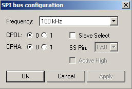
In the "Frequency" drop list you can choose the clock frequency of the SPI bus. The frequency should be less than or equal to the maximum frequency the SPI slave device supports. It can have value up to 200 kHz.
In addition to setting the clock frequency, the SPI master device must also configure the clock polarity ("CPOL") and clock phase ("CPHA").
Clock phase and polarity should be identical for the SPI master device and the communicating SPI slave device. In some cases, the phase and polarity are changed between transmissions to allow a SPI master device to communicate with peripheral SPI slaves having different requirements.
The CPOL clock polarity control bit specifies an active high or low clock. The CPHA clock phase control bit selects one of two fundamentally different transmission formats:
CPHA=0. The first edge on the SCK line is used to clock the first data bit of slave into the SPI master and the first data bit of SPI master into the SPI slave. In some peripherals, the first bit of the slave's data is available at the slave data out pin as soon as the slave is selected. In this format, the first SCK edge is not issued until a half cycle into the 8-cycle transfer operation. The first edge of SCK is delayed a half cycle by clearing the CPHA bit.
CPHA=1. Some peripherals require the first SCK edge before the first data bit becomes available at the data out pin; the second edge clocks data into the system. In this format, the first SCK edge is issued by setting the CPHA bit at the beginning of the 8-cycle transfer operation.
Select the "Slave Select" check-box if the connected SPI slave device supports the SPI slave selection. The "SS Pin" drop list allows to choose the slave select pin of U2C-12 adapter to which SPI slave device is connected. The SPI master device must select only one SPI slave device at a time.
The "Active High" check-box allows to determine the active state of the Slave Select signal (state during the SPI transfer). When the slave select line is active, the SPI master device can operate with the SPI slave device. If the "Active high" check-box is not checked - Slave Select pin value will be changed from logical "1" to logical "0" before SPI transaction and returned back to logical "1" after the data is transmitted. If the "Active high" check-box is checked - Slave Select pin value will be changed from logical "0" to logical "1" before SPI transaction and returned back to logical "0" after the data is transmitted. You can use this mode while working with the Microwire bus.