Software Applications & Demos
DLN-series adapters are supplied with a variety of examples that cover almost every aspect of development. They are not all designed to be impressive when you run them, but their source code is carefully written to show good programming practices.
Software examples source code is included into DLN setup package, which can be downloaded from Downloads page.
This documentation lists complete, ready-to-use code samples and applications that correspond to different DLN-series adapters features. All examples are supplemented with detailed source code description and tips.
We also provide a number of ready to use applications. You can evaluate the DLN-series adapter with these applications or use them during your daily work. Most of these applications are also supplemented with the source code in a variety of programming languages.
See anything missing? Please send an e-mail to support@diolan.com, where we’re collecting suggestions for future DLN code samples, and we’ll do our best to make it available!
To help you quickly find the appropriate example, we divided them into the following categories:
SPI examples
SPI master interface examples.
SPI slave interface examples.
25 series SPI Flash programming examples.
AT45DB series SPI DataFlash programming examples.
I2C examples
I2C master interface examples.
I2C slave interface examples.
24 series I2C EEPROM programming examples.
GPIO examples
Single GPIO pin usage examples.
Configuring and using of multiple GPIO pins examples.
Additional interfaces
ADC examples.
UART examples.
PWM examples.
Pulse and frequency counter examples.
LEDs examples.
Generic examples
Generic examples show how to connect to the DLN series adapter from a variety of programming languages, get device and software version, work with several DLN-series adapters simultaneously.
Supported Programming Languages & Frameworks
Diolan is committed to making all of our technologies equally accessible from different programming languages. It doesn't matter what framework or technology you use. You can easily interface DLN-series adapter in the familiar surrounding.
If you need an example for additional programming language of framework, just send us an email to support@diolan.com. New samples are added frequently so check back often.
C/C++ examples are available for the following frameworks and technologies:
Command line C and C++ applications.
MFC C++ GUI examples.
Cross-platform QT C++ GUI examples.
.NET C++/CLI examples.
C# and VB.NET examples are available as Windows Form Applications.
There are LabView Instrument Driver and LabView examples available for all supported interfaces.
Most of the examples can work with all DLN-series adapters. They check if the specific feature is supported by the selected adapter and enables or disables the corresponding controls.
SPI Examples
The SPI (Serial Peripheral Interface) examples demonstrate SPI master and slave modules and events interface incorporated in DLN-series adapters.
 |
SPI Master Configuration SoftwareConfigures SPI master interface - SPI mode, frequency, slave select pins, SPI data frames size and SPI delays. |
 |
SPI Master Full-duplex Read/Write SoftwarePerforms synchronous full-duplex SPI transfer. |
 |
SPI Slave Configuration SoftwareConfigures SPI slave interface - SPI mode, frame size and SPI slave events. |
 |
SPI Slave Receive SoftwareYou can use "SPI Slave Receive" application to receive data from SPI slave device. |
SPI Master Configuration Software
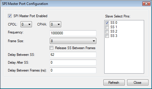
Use "SPI Master Port Configuration" software application to configure the SPI master interface of your DLN-series adapter. You can also configure the SPI master interface by clicking the "Configure" button in SPI Master Read/Write program.
Software Description
"SPI Master Port Configuration" software application allows you to configure the following SPI Master parameters:
- SPI Master Port Enabled
- This parameter allows to enable/disable SPI Master port. You should always enable this parameter before operating with SPI master interface. However you can change the states of other SPI Master parameters regardless of the state of current parameter.
- CPOL and CPHA
-
At CPOL=0 the base value of the clock is zero.
- For CPHA=0, data are captured on the clock's rising edge (low→high transition) and data are propagated on a falling edge (high→low clock transition).
- For CPHA=1, data are captured on the clock's falling edge and data are propagated on a rising edge.
At CPOL=1 the base value of the clock is one (inversion of CPOL=0).
- For CPHA=0, data are captured on clock's falling edge and data are propagated on a rising edge.
- For CPHA=1, data are captured on clock's rising edge and data are propagated on a falling edge.
- That is, CPHA=0 means sample on the leading (first) clock edge, while CPHA=1 means sample on the trailing (second) clock edge, regardless of whether that clock edge is rising or falling. Note that with CPHA=0, the data must be stable for a half cycle before the first clock cycle. For all CPOL and CPHA modes, the initial clock value must be stable before the chip select line goes active.
- Frequency
- This parameter allows to set SPI Master port frequency.
- DLN-1 USB-SPI Interface Adapter supports SPI clock frequency from 2 kHz up to 4 MHz.
- DLN-2 USB-SPI Interface Adapter supports SPI clock frequency from 2 kHz up to 18 MHz.
- DLN-4M and DLN-4S USB-SPI interface adapters are more powerful. They support SPI bus clock frequency up to 48 MHz, but the low frequency bound for them are only 376 kHz.
- Frame Size
- The size of the SPI frame.
- Release SS Between Frames
- Release the slave select line between successive SPI frames. Only for DLN-4M and DLN-4S adapters.
- Delay Between Frames
- Delay between successive SPI frames transmission. Only for DLN-4M and DLN-4S adapters.
- Delay After SS
- Delay after SS line assertion and before start of data transfer. Only for DLN-4M and DLN-4S adapters.
- Delay Between SS
- Delay after DLN-series adapter releases one SPI slave select line and before it asserts the another SPI slave select line. Only for DLN-4M and DLN-4S adapters.
- Slave Select Pins
- Slave Select pins to be asserted during the SPI transfer.
SPI Master Full-duplex Read/Write Software
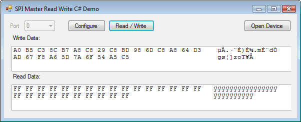
Use "SPI Master Read Write" software application to write and obtain data through SPI Interface.
Software Description
The following application components are available:
- Port" Combo-box
- Select available SPI Master port. Disabled if only one SPI port is available.
- "Configure" Button
- Press this button to open SPI Master configuration dialog. Read SPI Master Configuration page for details.
- "Open Device" Button
- Press this button to open or reopen device. Open Device Dialog Box will appear if several devices are connected to the same computer, so you will me able to select proper device.
- Write Data" Hex Field
- Type hex data to be sent to SPI Slave device.
- Read Data" Hex Field
- Read Hex data from the SPI Slave device.
- Read/Write" Button
- Press this button to execute Read/Write operation.
SPI Slave Configuration Software
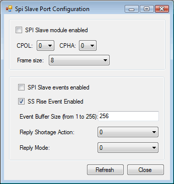
Use "SPI Slave Port Configuration" software application to configure the SPI slave interface of your DLN-series adapter. You can also configure the SPI slave interface by clicking the "Configure" button in SPI Slave Receive program.
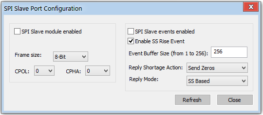
Software Description
"SPI Slave Port Configuration" software application allows you to configure the following SPI Slave parameters:
- SPI slave module enabled
- Enable or disable SPI Slave port.
- CPOL and CPHA
-
At CPOL=0 the base value of the clock is zero.
- For CPHA=0, data are captured on the clock's rising edge (low→high transition) and data are propagated on a falling edge (high→low clock transition).
- For CPHA=1, data are captured on the clock's falling edge and data are propagated on a rising edge.
At CPOL=1 the base value of the clock is one (inversion of CPOL=0).
- For CPHA=0, data are captured on clock's falling edge and data are propagated on a rising edge.
- For CPHA=1, data are captured on clock's rising edge and data are propagated on a falling edge.
That is, CPHA=0 means sample on the leading (first) clock edge, while CPHA=1 means sample on the trailing (second) clock edge, regardless of whether that clock edge is rising or falling. Note that with CPHA=0, the data must be stable for a half cycle before the first clock cycle. For all CPOL and CPHA modes, the initial clock value must be stable before the chip select line goes active.
- Frame size
- The size of the SPI frame. SPI frame size can be from 6 to 16 bits.
- SPI slave events enabled
- Enable of disable fixation of the SPI slave events.
- SS Rise Event Enabled
- Enable or disable fixation of the SS rise events.
- Event Buffer Size
- The size of event buffer.
- Reply Shortage Action
- The are 2 parameters available: send zeros or resend last buffer.
- Reply Mode
- Set the SPI slave reply mode. There are 3 types available: Off, SS based, count based.
SPI Slave Receive Software
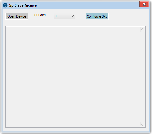
You can use "SPI Slave Receive" software to receive data from SPI slave device.
Software Description
The following application components are available:
- Port" Combo-box
- Select available SPI slave port.
- "Configure" Button
- Press this button to open SPI Slave configuration dialog. Read SPI Slave Configuration page for details.
- "Open Device" Button
- Press this button to open or reopen device. Open Device Dialog Box will appear if several devices are connected to the same computer, so you will be able to select proper device.
- Log Field
- The available data and events logs are posted to this field.