SPI Bus
The Serial Peripheral Interface (SPI) is a synchronous serial data interface, developed by Motorola. It is used for connecting various peripheral devices. SPI operates either in full-duplex or in half-duplex mode and can transfer data over short distances at high speeds. During data transfer devices can work either in master or in slave mode. The source of synchronization is the system clock, which is generated by the master. The SPI interface allows to connect one or more slave devices to a single master device via the same bus.

SPI Key Features
- Read, write and full-duplex (simultaneous read/write) data transactions;
- SPI master and SPI slave configuration;
- Configurable SPI bus clock polarity, phase and frequency;
- Configurable number of bits to transfer;
- Communication with serial external devices (ADC and DAC, RTC, temperature and pressure sensors, LCD controller, etc.).
SPI Benefits
- SPI is considered the fastest synchronous serial data transfer interface;
- SPI is a very simple communication protocol;
- Supports full-duplex communication;
SPI Drawbacks
- Requires more traces on the board (X + 3, where X is the number of slave devices);
- No hardware flow control;
- No slave acknowledgment;
- May prone to noise spikes causing faulty communication.
SPI Structure
To understand the SPI interface structure, first, we need to look at its lines. There are 4 lines in total (2 data lines and 2 service lines):
- CS (chip select) or SS (slave select) line - allows/disallows operation with slave device.
- MISO (Master input slave output) data line - data can be transferred from slave to master over this line.
- MOSI (Master output slave input) data line - data can be transferred from master to slave device over this line.
- CLK (clock) line - Clock signal.
When the signal from CS service line is inverted (equals to 1) slave device is inactive, when CS signal equals to 0, master device can transfer or receive data to/from slave device. This line allows to connect several slave devices to master, so we can choose the slave device for data transfer over SPI interface.
Another service line is CLK. It generates clock signal. While data is transferred over SPI interface, CLK line is also generating clock signal. Its frequency determines the data transfer speed over SPI. CLK signal is transferred with the same frequency as data flows. Thus there is no need to synchronize the transfer speed of master and slave devices.
MOSI (Master Output Slave Input) line - data line which is used for data transferring from master device to slave device.
MISO (Master Input Slave Output) line - data line, which is used for data transferring from slave device to master device.
Configurable SPI Delays
Sometimes slave devices need additional time to process data. In order to provide this time DLN-series adapters can insert delays at different data transmission stages. Those are delay between frames, delay after slave selection and delay between slave selection. All of the delays are set in nanoseconds and have to be adjusted only once. After configuring the delays are applied to all the SS lines.
Delay Between SPI Frames
In case a slave device is not fast enough to process continuously incoming data, a user can configure the DLN adapter to insert delays between each two consecutive frames. This gives the slave device additional time to process the data from the previous frame. Once enabled, the delay is inserted after each frame. The delay value is adjusted using the DlnSpiMasterSetDelayBetweenFrames() function. The current delay between frames value can be retrieved by calling the DlnSpiMasterGetDelayBetweenFrames() function.
Delay After Slave Selection
When SPI slave device needs additional time for initialization, a Delay After Slave Selection (SS) can be used. When enabled, it is placed after an SS line assertion and before the first frame transmission. The delay value is adjusted using the DlnSpiMasterSetDelayAfterSS() function. You can retrieve the current delay value by calling the DlnSpiMasterGetDelayAfterSS() function.
Delay Between Slave Selection
Delay Between Slave Selection is inserted between one SS line release and assertion of another SS line. The delay value is adjusted using the DlnSpiMasterSetDelayBetweenSS() function, and can be retrieved using the DlnSpiMasterGetDelayBetweenSS() function.
SPI Frames
A frame is a single portion of data sent through SPI bus. Some of the DLN adapters support adjustable frame size. The frame data are transferred starting from the most significant bit and up to the least significant bit.

In case the frame size is set to 8 bits or less, only one byte is needed to store the frame data. If the frame size is lesser than 8 bits, the least significant bits of the byte will be transferred, while extra (most significant) bits will be discarded, regardless of their content. The DlnSpiMasterReadWrite() function can be called to transmit array of 8-bit and smaller frames.
In case a frame size is 9-16 bits, two bytes are needed to store the frame data. You can allocate an array of up to 128 16-bit integers. These integers must be stored inside the array in Little Endian format. This shouldn't cause a problem, since Little Endian format is used for data storage by most of modern computers. If the frame size is less than 16 bits, 2-byte integers will be used. The least significant bits of the integer will be transferred, while extra (most significant) bits will be discarded, regardless of their content.
The size of the frame does not limit the size of the buffer to be transferred. DlnSpiMasterReadWrite() (DlnSpiMasterReadWrite16()) function accepts buffer sizes of up to 256 bytes. You can call the function several times to send a larger buffer.
Splitting the data transfer into frames allows to set delays and configure SS line release between the frames. By default no delays are set and SS line remains asserted all the time.
SPI Operation Modes
SPI Full Duplex Mode
In full duplex mode SPI master device simultaneously transmits data to a slave and receives data from a slave. This way only a single slave device can be engaged at one time. An SS line is used to select the particular SPI slave device.
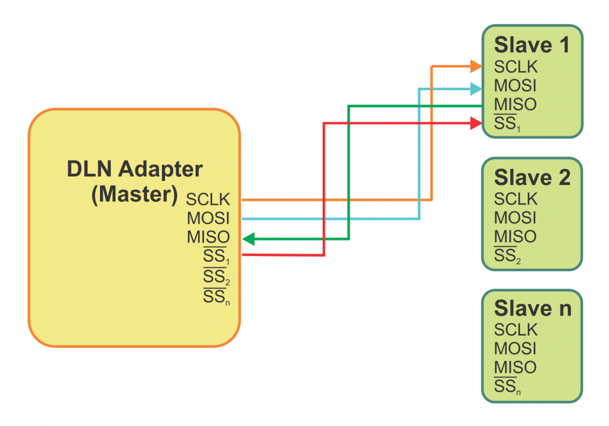 SPI in full duplex mode
SPI in full duplex mode
SPI Half Duplex Mode (Single Read)
In half duplex single read mode SPI master device only receives data from a slave. This way only a single slave device can be engaged at one time. An SS line is used to select the slave device.
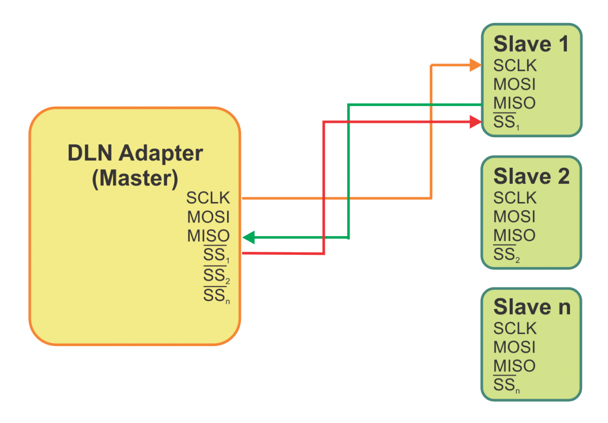 SPI in half duplex single read mode
SPI Half Duplex Mode (Single Write)
In half duplex single write mode SPI master device only transmits data to a slave, and doesn't receive any data from the slave. This way simultaneous operation with several slave devices is possible.
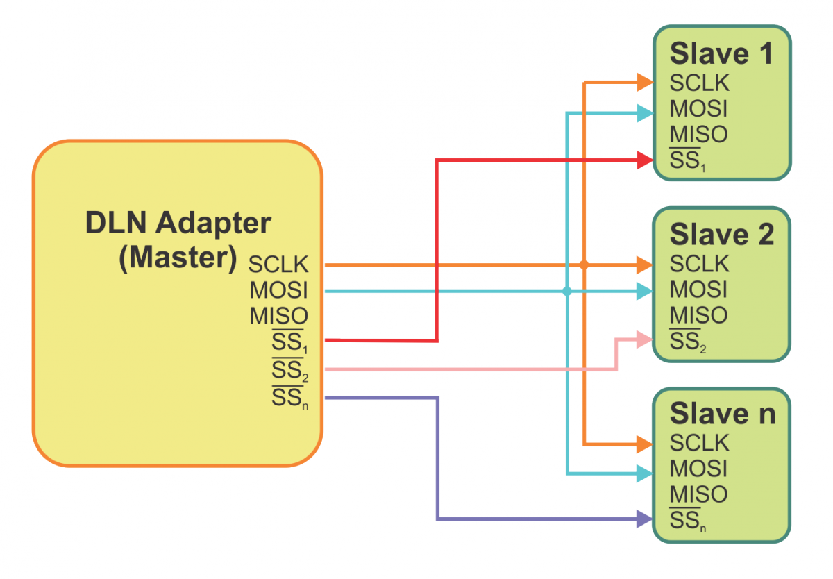 SPI in half duplex single write mode
SPI Slave Selection
There is different number of available SS lines for each DLN-series adapter. There is 1 SS line for DLN-1 adapter, there are 5 SS lines for DLN-2 and 4 SS lines for DLN-4M/S adapters. If you need more SS lines you can use unengaged GPIO pins as well.
An SS line is used to select an SPI slave device. Slave device is selected by calling the DlnSpiMasterSetSS() function.
Selecting Single SPI Slave Device
If you use the DLN-series adapter in Full Duplex or Half Duplex (Single Read) mode, you can only select one slave device at a time.

In order to deactivate all devices send a 0xFF (1111 1111) value. A slave device can be selected by changing the corresponding bit value to 0.
Example: Slave device #01 can be selected by calling the DlnSpiMasterSetSS() function and passing 0xFD (1111 1101) value as the ss parameter.
Selecting Several SPI Slave Devices At Once
If you use the DLN-series adapter in Half Duplex (Single Write) mode, you can activate several slave devices at once.

A user can address the required slave devices by changing the respective bit values to 0.
Example: Slave device #00 and #02 can be activated by calling the DlnSpiMasterSetSS() function and passing the 0xFA (1111 1010) value as the ss parameter.
Addressing up to 15 SPI Slave Devices
If you connect the ss lines to an external decoder/demultiplexer, you will be able to connect more slave devices to single DLN-series adapter.
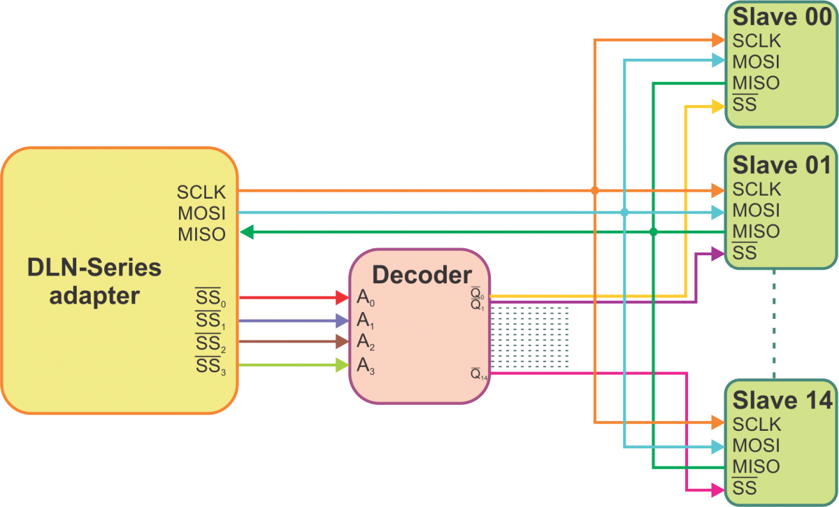
In order to use this feature you need an external decoder/demultiplexer (e.g. 74HC4515). With a decoder/demultiplexer connected, the SS lines are used to send a 4-bit value. A user can address the necessary slave by sending its number (values from 0 to 15). The numbers 0 to 14 represent the number of the slave device, while 15 means that no device is selected. This means you can connect up to 15 slave devices to the DLN-series adapter.
Example: Slave device #11, can be activated by calling the DlnSpiMasterSetSS() function and passing the 0xFB (1111 1011) value as the ss parameter.
SPI Transfer Modes
SPI interface allows to transmit and receive data simultaneously on two lines (MOSI and MISO). Clock polarity (CPOL) and clock phase (CPHA) are the main parameters that define a clock format to be used by the SPI bus. Depending on CPOL parameter, SPI clock may be inverted or non-inverted. CPHA parameter is used to shift the sampling phase. If CPHA=0 the data are sampled on the leading (first) clock edge. If CPHA=1 the data are sampled on the trailing (second) clock edge, regardless of whether that clock edge is rising or falling.
CPOL=0, CPHA=0
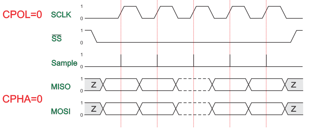
The data must be available before the first clock signal rising. The clock idle state is zero. The data on MISO and MOSI lines must be stable while the clock is high and can be changed when the clock is low. The data is captured on the clock's low-to-high transition and propagated on high-to-low clock transition.
CPOL=0, CPHA=1
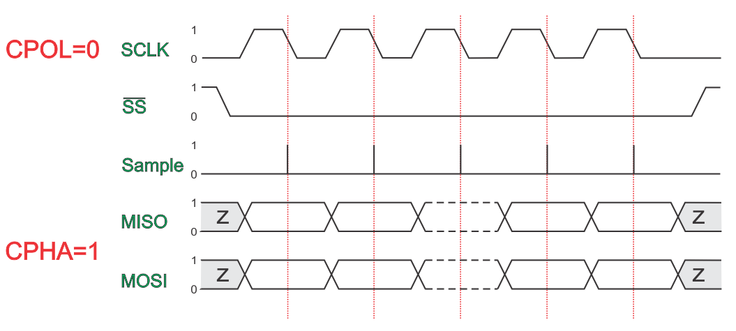
The first clock signal rising can be used to prepare the data. The clock idle state is zero. The data on MISO and MOSI lines must be stable while the clock is low and can be changed when the clock is high. The data is captured on the clock's high-to-low transition and propagated on low-to-high clock transition.
CPOL=1, CPHA=0
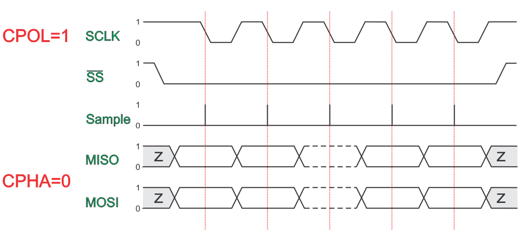
The data must be available before the first clock signal falling. The clock idle state is one. The data on MISO and MOSI lines must be stable while the clock is low and can be changed when the clock is high. The data is captured on the clock's high-to-low transition and propagated on low-to-high clock transition.
CPOL=1, CPHA=1
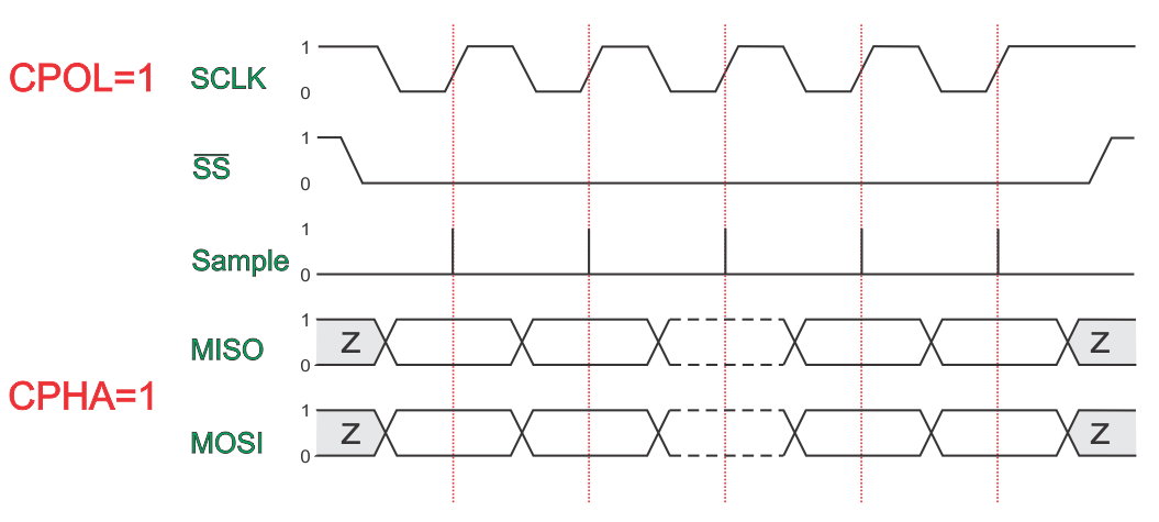
The first clock signal falling can be used to prepare the data. The clock idle state is one. The data on MISO and MOSI lines must be stable while the clock is high and can be changed when the clock is low. The data is captured on the clock's low-to-high transition and propagated on high-to-low clock transition.
SS Line Release Between Frames Theory
By default, SPI data transmission between a master and a slave looks like this.
 SS release between frames is disabled.
However, some slave devices require SS line to be released and deasserted between data frames.
 SS release between frames is enabled.
In this case an SS line is released after each frame and asserted before the next frame. If delay between frames is specified, the SS line will be released for the whole delay duration. Yet, the line will still be released and asserted between data frames even if this delay is zero.


