Control Panel Application
Control Panel application is distributed with open source code. Its source code is included in I2C Bridge.X.X.X.exe installation package.
Control Panel Main Window
To launch the application open "Start Menu\Programs\Diolan U2C-12" or "C:\Program Files\Diolan\U2C-12\bin" and run the Control Panel.
When the Control Panel is started, the application main window will appear (Figure 2.1, “The Control Panel main window”).
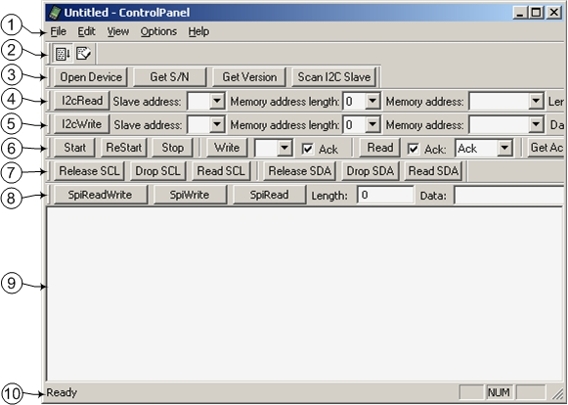
The application main window contains the following elements (enumeration of elements in the list agrees with enumeration on (Figure 2.1, “The Control Panel main window”):
Main menu;
Standard toolbar;
"I2C Bridge Devices" bar;
"I2C Read" Bar, it is used to read the data from I2C slave device;
"I2C Write" Bar, it is used to write the data to I2C slave device;
"I2C Low Level" Bar, it is used to work with I2C slave device on low level;
"I2C Bus Level" Bar, it is used to work withI2C slave device on wire level;
"SPI Bus" Bar, it is used to read/write into SPI slave device;
Log field;
Status line.
Main Menu and Toolbar
Control Panel main menu consists of following items:
- The "File" menu item:
Exit - Close the application.
- The "Edit" menu item:
Clear Log - Clear log field.
- The "View" menu item:
Exit - Close the application.
- The "View" menu item:
Standard Toolbar - Show/hide Standard toolbar;
Status Bar - Show/hide Status Bar;
I2C Bridge Devices Bar - Show/hide I2C Bridge Devices Bar;
I2C Read Bar - Show/hide I2C Read Bar;
I2C Write Bar - Show/hide I2C Write Bar;
I2C Read Bar - Show/hide I2C Read Bar;
I2C Low Level Bar - Show/hide I2C Low Level Bar;
I2C Bus Level Bar - Show/hide I2c Bus Level Bar;
SPI Bus Bar - Show/hide SPI Bus Bar.
- The "Options" menu item:
Auto Scroll - Turn on/off auto scroll mode for new logs in log the field;
I2C Configuration - Show dialog window for changing I2C bus working mode parameters;
Spi Configuration - Show dialog window for changing SPI bus working mode parameters.
- The "Help" menu item:
About Control Panel... - Show "About" dialog window.
Standard Toolbar contains following buttons:
"I2C Configuration" Dialog Window
In the “I2C Configuration” dialog window (Figure 2.2, ““I2C Configuration” dialog window”) you can change the settings of the I2C bus. To open this dialog window select "Options/I2C Configuration".
Figure 2.2. “I2C Configuration” dialog window
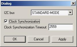
In the "I2C bus" drop list you can choose the frequency of the I2C bus. It can have one of the following values:
Fast mode (400 kHz);
Standard mode (100 kHz);
Any value in the range 2 kHz – 83 kHz.
Select the “Clock Synchronization” check-box to turn on the clock synchronization (Clock Stretching). This option is only available for the frequencies below or equal to "Standard-mode" (<=100 kHz). In "Fast-mode" this option is unavailable.
The “Clock Synchronization Timeout” field allows to change the clock stretching timeout value (integer number from 1 to 65535). Clock synchronization (clock stretching) timeout value specified as multiple of 100 microseconds.
"I2C Bridge Devices" Bar
The "I2C Bridge Devices" Bar (Figure 2.4, “"I2C Bridge Devices" Bar”) includes the following buttons:
Figure 2.4. "I2C Bridge Devices" Bar
“Open Device” button
Click to choose one of the U2C-12 adapters connected to the PC. If only one U2C-12 adapter is connected, it becomes selected automatically. If several U2C-12 adapters are connected to the same PC, the “Device Open” dialog window will appear (Figure 2.5, ““Open Device” dialog window”). You can use the device serial number to open the specific adapter.
Figure 2.5. “Open Device” dialog window
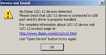
If there are no connected U2C-12 adapters, the “Device not found” message (Figure 2.6, ““Device not found” message”) will be displayed.
Figure 2.6. “Device not found” message
When Control Panel application is started it opens the device. The “Open Device” button can be used by user for switching to the new adapter after it was connected.
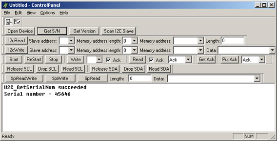
- “Get S/N” button
Each of the U2C-12 adapters has the unique serial number. To view the serial number of your U2C-12 adapter you can use the “Get S/N” button. The U2C-12 adapter serial number is displayed in log field (Figure 2.7, “Information about serial number of U2C-12 adapter”).
Figure 2.7. Information about serial number of U2C-12 adapter
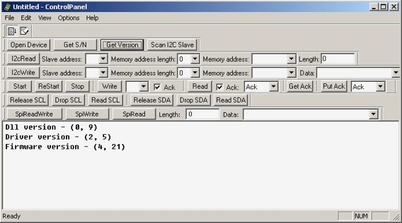
- “Get Version” button
The “Get Version” button displays U2C-12 adapter software version in the log field. (Figure 2.8, “Information about U2C-12 adapter software and firmware version”).
Figure 2.8. Information about U2C-12 adapter software and firmware version
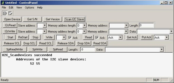
“Scan I2C Slave” button
The “Scan I2C Slave” button scans the I2C slave device addresses currently occupied by the I2C slave devices which are connected to the U2C-12 adapter. The I2C slave device addresses are displayed in the log field in hexadecimal format (Figure 2.9, “The I2C slave device addresses”). They are also added to “Slave address” drop list of “I2C Write” and “I2C Read” bars. U2C-12 adapter supports 7-bit addressing format.
Figure 2.9. The I2C slave device addresses
"I2C Read" Bar
I2C Read” Bar (Figure 2.10, ““I2C Read” Bar”) is used to read data from I2C slave device.
Figure 2.10. “I2C Read” Bar
Each I2C slave device has its own 7-bit address. Enter it in the “Slave address” field. The I2C slave device address is an integer hexadecimal number in the range from 0 to 7F. Click the “Scan I2C Slave” button (Figure 2.9, “The I2C slave device addresses”) to get the list of addresses currently occupied by I2C slave devices.
Some I2C slave devices (e.g. I2C EEPROMs) have their own internal addressing. If your I2C slave device supports internal addressing, you can enter the internal address in the "Memory address" field and the address length (in bytes) in the “Memory address length” field. If your I2C slave device doesn’t support the internal addressing, enter “0” in the “Memory address length” field. Memory address length depends on the I2C slave device type. If the memory address length value is incorrect, you will get the wrong data.
Possible memory address values for the particular memory address length are listed in table.
| Memory address length value | Memory address values range |
|---|---|
| 1 | 0-FF |
| 2 | 0-FFFFFF |
| 4 | 0-FFFFFFFF |
Enter the number of bytes to be read from the I2C slave device into the “Length” field (integer decimal value from 1 to 256).
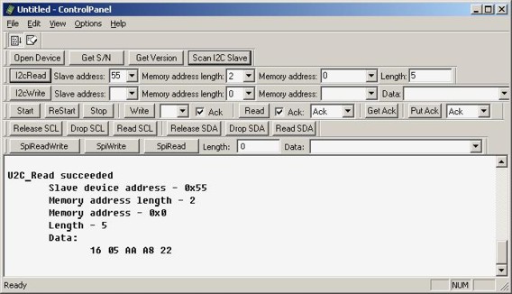
After you have entered the correct values, press the “I2c Read” button to read the data from the I2C slave device. You can see the result in the log field (Figure 2.11, “The result of the data reading from the I2C slave device”).
Figure 2.11. The result of the data reading from the I2C slave device
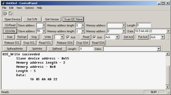
"I2C Write" Bar
Figure 2.12. The "I2C Write" Bar
Each I2C slave device has its own 7-bit address. Enter it in the “Slave address” field. The I2C slave device address is an integer hexadecimal number in the range from 0 to 7F. Click the “Scan I2C Slave” button (Figure 2.9, “The I2C slave device addresses”) to get the list of addresses currently occupied by the I2C slave devices.
Some I2C slave devices (e.g. I2C EEPROMs) have their own internal addressing. If your I2C slave device supports internal addressing, you can enter the internal address in the "Memory address" field and the address length (in bytes) in the “Memory address length” field. If your I2C slave device doesn’t support the internal addressing, enter “0” in the “Memory address length” field. Memory address length depends on the I2C slave device type. If the memory address length value is incorrect, you will get the wrong data.
The possible memory address values for the particular memory address length are listed in table.
| Memory address length value | Memory address values range |
|---|---|
| 1 | 0-FF |
| 2 | 0-FFFFFF |
| 4 | 0-FFFFFFFF |
In the “Data” field you can enter the data to be sent to the I2C slave device. You can type hexadecimal values (from 0 to FF) to the field. To enter more then one value separate them by space.
After you have entered the correct values press the “I2с Write” button to send the data to the I2C slave device. You can see the result in the log field Figure 2.13, “The result of data writing into the I2C slave device”.
Figure 2.13. The result of data writing into the I2C slave device
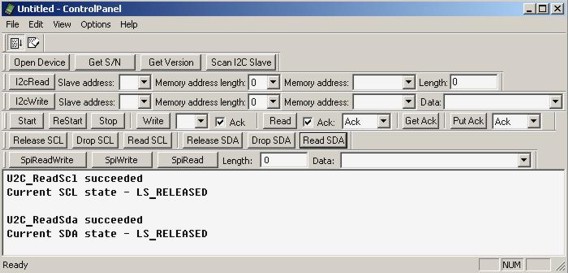
"I2C Bus Level" Bar
The "I2C Bus Level" Bar (Figure 2.19, “"I2C Bus Level" Bar”) allows to work with the I2C slave devices on the bus level (SDA and SCL lines). The bar buttons make it possible to read and write the data by controlling the bus lines.
Figure 2.19. "I2C Bus Level" Bar
The "Release SCL" button releases the SCL line of the I2C bus. If the SCL line is not pulled down by I2C slave device, it will get high.
The "Drop SCL" pulls down the I2C bus SCL line.
The "Read SCL" button checks the current state of the I2C bus SCL line.
The "Release SDA" button releases the SDA line of the I2C bus. If the line is not pulled down by I2C slave device, it will get high.
The "Drop SDA" button pulls down the I2C bus SDA line.
The "Read SDA" button checks the current state of the I2C bus SDA line.
For instance, by consiquent pressing the "Read SCL" and "Read SDA" buttons (on condition that the I2C bus is released) the messages informing that the both lines are released will be displayed in the log field (Figure 2.20, “Reading the SDA/SCL lines”).
Figure 2.20. Reading the SDA/SCL lines
"I2C Low Level" Bar
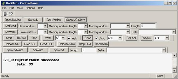
The “I2C Low Level” bar (Figure 2.14, “"I2C Low Level" Bar”) allows to work with the I2C slave devices on the low level.
Figure 2.14. "I2C Low Level" Bar
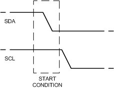
The “Start” button generates the START condition on the I2C bus, i.e. a HIGH to LOW transition of the SDA line while the SCL line is HIGH. The START condition (Figure 2.15, “The START condition”) indicates the beginning of the data exchange operation.
Figure 2.15. The START condition
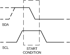
The “ReStart” button generates the repeated START condition (Figure 2.16, “The repeated START condition”). It is used to allow combined write/read operations without releasing the bus and interrupting the operation.
Figure 2.16. The repeated START condition
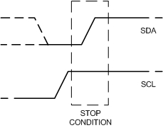
The “Stop” button generates the STOP condition (Figure 2.17, “The STOP condition”) on the I2C bus, i.e. a HIGH to LOW transition of the SDA line while the SCL line is HIGH. The bus is considered to be free after the STOP condition.
Figure 2.17. The STOP condition
The “Write” button transmits the data byte from I2C master to I2C slave device. Enter the transmitted value into the “Write” field (integer hexadecimal value from 0 to FF).
If the "Ack" (Write) check-box is selected, acknowledge will be requested from the I2C slave device after the data byte transmission.
If the "Ack" (Write) check-box is not selected, acknowledge will not be requested. It may lead to the data loss. You can still press the "Get Ack" button to request acknowledge.
The “Read” button transmits the data byte from I2C slave to I2C master device. The information about the byte data requested is desplayed in the log field (Figure 2.18, “The information about the byte data reading with the "Ack" signal”).
Figure 2.18. The information about the byte data reading with the "Ack" signal
If the "Ack" (read) check-box is selected, acknowledge ("Ack" or "No Ack" depends on the value of “Put Ack” drop list) will be generated.
If "Ack" (read) check-box is not selected, acknowledge will not be generated. You can still press the “Put Ack” button to generate acknowledge. Without acknowledge the further data reading can be incorrect.
The “Get Ack” button requests acknowledge from the I2C slave device.
The “Put Ack” button generates acknowledge on the I2C bus ("Ack” or “No Ack” depends on the value of “Put Ack” drop list).
"SPI Bus Configuration" Dialog Window
In the “SPI Bus Configuration” dialog window (Figure 2.3, ““Spi Bus Configuration” dialog window”) you can change the settings of the SPI bus. To open this dialog window select "Options/Spi Configuration".
Figure 2.3. “Spi Bus Configuration” dialog window
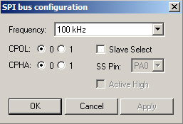
In the "Frequency" drop list you can choose the clock frequency of the SPI bus. The frequency should be less than or equal to the maximum frequency the SPI slave device supports. It can have value up to 200 kHz.
In addition to setting the clock frequency, the SPI master device must also configure the clock polarity ("CPOL") and clock phase ("CPHA").
Clock phase and polarity should be identical for the SPI master device and the communicating SPI slave device. In some cases, the phase and polarity are changed between transmissions to allow a SPI master device to communicate with peripheral SPI slaves having different requirements.
The CPOL clock polarity control bit specifies an active high or low clock. The CPHA clock phase control bit selects one of two fundamentally different transmission formats:
CPHA=0. The first edge on the SCK line is used to clock the first data bit of slave into the SPI master and the first data bit of SPI master into the SPI slave. In some peripherals, the first bit of the slave's data is available at the slave data out pin as soon as the slave is selected. In this format, the first SCK edge is not issued until a half cycle into the 8-cycle transfer operation. The first edge of SCK is delayed a half cycle by clearing the CPHA bit.
CPHA=1. Some peripherals require the first SCK edge before the first data bit becomes available at the data out pin; the second edge clocks data into the system. In this format, the first SCK edge is issued by setting the CPHA bit at the beginning of the 8-cycle transfer operation.
Select the "Slave Select" check-box if the connected SPI slave device supports the SPI slave selection. The "SS Pin" drop list allows to choose the slave select pin of U2C-12 adapter to which SPI slave device is connected. The SPI master device must select only one SPI slave device at a time.
The "Active High" check-box allows to determine the active state of the Slave Select signal (state during the SPI transfer). When the slave select line is active, the SPI master device can operate with the SPI slave device. If the "Active high" check-box is not checked - Slave Select pin value will be changed from logical "1" to logical "0" before SPI transaction and returned back to logical "1" after the data is transmitted. If the "Active high" check-box is checked - Slave Select pin value will be changed from logical "0" to logical "1" before SPI transaction and returned back to logical "0" after the data is transmitted. You can use this mode while working with the Microwire bus.
"SPI Bus" Bar
The "SPI Bus Level" Bar (Figure 2.21, “The "SPI Bus" bar”) allows to read and write the data over the SPI bus.
Figure 2.21. The "SPI Bus" bar
The "Spi ReadWrite" button shifts out (writes) and in (reads) a stream of up to 256 bytes to/from the SPI slave device. The shift operation is occurred in a full duplex data transmission mode.
The "Spi Write" button shifts out (writes) a stream of up to 256 bytes to the SPI slave device.
The "Spi Read" button shifts in (reads) a stream of up to 256 bytes from the SPI slave device.
The "Length" field allows you to enter the number of bytes to be shifted. Maximum value is 256.
The "Data" field allows you to enter the data to be shifted. You can type hexadecimal values (from 0 to FF) to the field. To enter more then one value separate them by space.