DLN-2-U2C API (U2C-12)
USB-I2C/SPI/GPIO Interface Adapter - DLN-2-U2C (U2C-12) is a USB to I2C master, SPI and GPIO controller. U2C-12 adapter is assigned to access your hardware from PC using I2C, SPI interfaces and GPIO.
I2C Bridge is the program package for working with U2C-12 adapter in Windows OS. I2C Bridge includes the drivers for U2C-12 adapter and the software to operate it. I2C Bridge also includes the libraries, the source files, the documentation and the demo applications.
U2C-12 Installation
System Requirements
To run I2C Bridge software and U2C-12 adapter on your PC you should have:
- MS Windows 98/2000/NT/XP, Linux, FreeBSD, NetBSD, OpenBSD, Darwin, MacOS;
- At least 256 Mb of RAM;
- Available USB port.
Some of the U2C Bridge applications work only in Windows OS.
Driver Signing Settings
Before plugging in U2C-12 adapter, the necessary software (I2C Bridge) should be installed. Before the installation, it is recommended to check Windows OS settings:
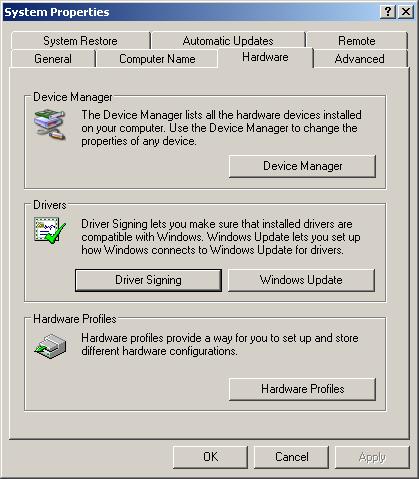
Choose "My Сomputer/Properties";
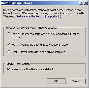
In "System Properties" window select the "Hardware" tab and press the "Driver Signing" button;
In the "Driver Signing Options" dialog window (Figure 1.2, “The "Driver Signing Options" window”) select "Ignore" or "Warn". In case you choose "Block" hardware drivers installation will be blocked by Windows OS.
Installing I2C Bridge
To install U2C-12 adapter software:
Load the latest version of I2C Bridge program package from Diolan website ( http://www.diolan.com/products/u2c12/downloads.html);
Run I2C Bridge.X.X.X.exe file ("X.X.X" is the number of current version);
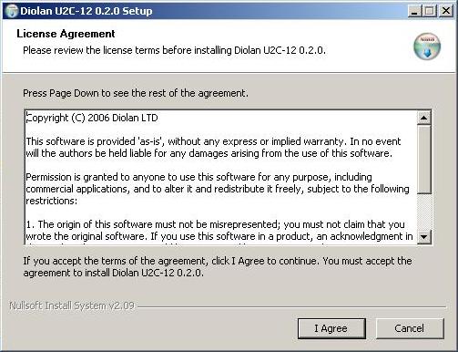
Read the license agreement (Figure 1.3, “The "License Agreement" window”). In case you agree with all license conditions press the “I Agree” button. The Setup process will continue;
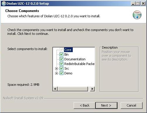
In the next window (Figure 1.4, “Choosing the necessary application components”) choose necessary application components and press the "Next" button;
The list of application components:
- Core
U2C-12 device drivers and library installation;
- Bin
Compiled and ready to use binary files;
- Documentation
U2C-12 Development Kit Documentation;
- Redistributable Packet
U2C-12 redistribution packet;
- Src
Source code;
- Demo
Demo applications.
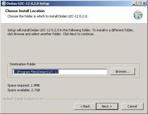
In the "Choose Install Location" window (Figure 1.5, “Choosing folder for Diolan U2C-12 installation”) choose the folder in which to install the Diolan USB-I2C/SPI/GPIO Interface Adapter software. Then press the “Next” button;
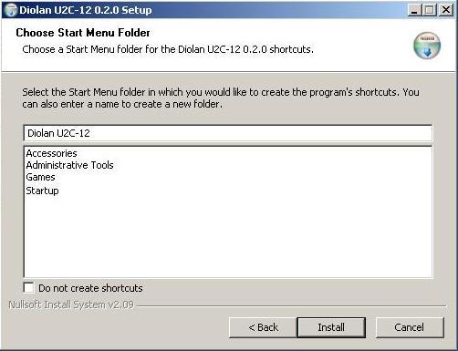
In the "Choose Start Menu Folder" window (Figure 1.6, “Choosing "Start Menu/Programs" folder for the Diolan U2C-12 shortcuts”) choose the "Start Menu" folder for the Diolan U2C-12 software shortcuts. If you select the “Do not create shortcuts” check-box, the shortcuts for installed applications will not be created. Press “Install” button and wait until the installation is completed;
After installation is completed press the “Close” button.
U2C-12 Hardware Drivers Installation
Connect U2C-12 adapter to PC with USB cable. After connection of U2C-12 adapter the “Found New Hardware Wizard” is started:
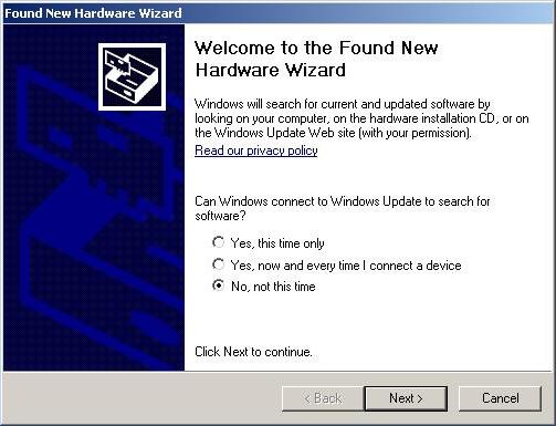
Select the "No, not this time" item in the "Found New Hardware Wizard" window (Figure 1.7, “"Found New Hardware Wizard" start window”) and press the "Next" button;
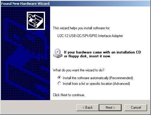
In next window (Figure 1.8, “"Found New Hardware Wizard" window for choosing searching options”) choose the "Install the software automatically" item and press the “Next” button;
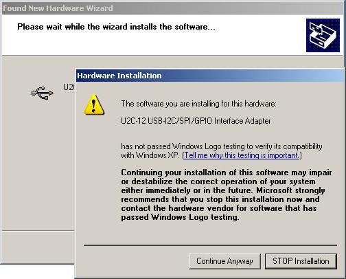
In case of the "Hardware installation" window appearance (Figure 1.9, “The "Hardware installation" window appearance”) press the "Continue Anyway" button;
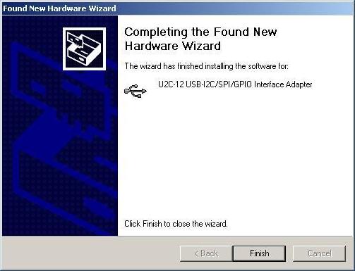
After the installation is completed, press the “Finish” button (Figure 1.10, “The “Found New Hardware Wizard" completing window”).
Figure 1.10. The “Found New Hardware Wizard" completing window
Linux (OpenSuse) libusb User Permissions Issue
- Problem:
There is a necessity to install U2C-12 adapter driver without running I2CBridge.x.x.x.exe setup file. Let's assume, you want to install U2C-12 device driver and your own application on your client's computer and there is no need to install Diolan software too.
- Solution:
Here is available solution:
After you've installed I2CBridge application, inside the U2C-12 program folder you can find a Driver folder which contains U2C-12 device driver files. To properly install U2C-12 adapter driver on computer you need to perform the following steps:
Copy I2cBrdg.SYS and I2cBrdgf.SYS drivers to "%windir%\system32\drivers\" folder;
Copy I2cBrdg.inf file to "%windir%\inf\" folder;
Copy i2cbrdg.dll to "%windir%\system32\" folder or to the same folder your application is launched from.
%windir% contains the address line to Windows system folder where your operating system is installed.
In case you want to perform this actions manually, you may mention that there is no inf folder inside Windows system folder. By default the inf folder is hidden. To make it visible, open Windows Explorer, select "Tools" main menu item and choose "Folder Options". In "Folder Options" window select "View" tab. In "Advanced settings" section find "Hidden files and folders" and choose "Show hidden files and folders" radio button. Then click "OK" button. Now you can see all hidden files and folders in your operating system.
Driver Installation without Setup File Execution
- Problem:
There is a necessity to install U2C-12 adapter driver without running I2CBridge.x.x.x.exe setup file. Let's assume, you want to install U2C-12 device driver and your own application on your client's computer and there is no need to install Diolan software too.
- Solution:
Here is available solution:
After you've installed I2CBridge application, inside the U2C-12 program folder you can find a Driver folder which contains U2C-12 device driver files. To properly install U2C-12 adapter driver on computer you need to perform the following steps:
Copy I2cBrdg.SYS and I2cBrdgf.SYS drivers to "%windir%\system32\drivers\" folder;
Copy I2cBrdg.inf file to "%windir%\inf\" folder;
Copy i2cbrdg.dll to "%windir%\system32\" folder or to the same folder your application is launched from.
%windir% contains the address line to Windows system folder where your operating system is installed.
In case you want to perform this actions manually, you may mention that there is no inf folder inside Windows system folder. By default the inf folder is hidden. To make it visible, open Windows Explorer, select "Tools" main menu item and choose "Folder Options". In "Folder Options" window select "View" tab. In "Advanced settings" section find "Hidden files and folders" and choose "Show hidden files and folders" radio button. Then click "OK" button. Now you can see all hidden files and folders in your operating system.
Control Panel Application
Control Panel application is distributed with open source code. Its source code is included in I2C Bridge.X.X.X.exe installation package.
Control Panel Main Window
To launch the application open "Start Menu\Programs\Diolan U2C-12" or "C:\Program Files\Diolan\U2C-12\bin" and run the Control Panel.
When the Control Panel is started, the application main window will appear (Figure 2.1, “The Control Panel main window”).
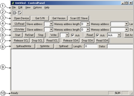
The application main window contains the following elements (enumeration of elements in the list agrees with enumeration on (Figure 2.1, “The Control Panel main window”):
Main menu;
Standard toolbar;
"I2C Bridge Devices" bar;
"I2C Read" Bar, it is used to read the data from I2C slave device;
"I2C Write" Bar, it is used to write the data to I2C slave device;
"I2C Low Level" Bar, it is used to work with I2C slave device on low level;
"I2C Bus Level" Bar, it is used to work withI2C slave device on wire level;
"SPI Bus" Bar, it is used to read/write into SPI slave device;
Log field;
Status line.
Main Menu and Toolbar
Control Panel main menu consists of following items:
- The "File" menu item:
Exit - Close the application.
- The "Edit" menu item:
Clear Log - Clear log field.
- The "View" menu item:
Exit - Close the application.
- The "View" menu item:
Standard Toolbar - Show/hide Standard toolbar;
Status Bar - Show/hide Status Bar;
I2C Bridge Devices Bar - Show/hide I2C Bridge Devices Bar;
I2C Read Bar - Show/hide I2C Read Bar;
I2C Write Bar - Show/hide I2C Write Bar;
I2C Read Bar - Show/hide I2C Read Bar;
I2C Low Level Bar - Show/hide I2C Low Level Bar;
I2C Bus Level Bar - Show/hide I2c Bus Level Bar;
SPI Bus Bar - Show/hide SPI Bus Bar.
- The "Options" menu item:
Auto Scroll - Turn on/off auto scroll mode for new logs in log the field;
I2C Configuration - Show dialog window for changing I2C bus working mode parameters;
Spi Configuration - Show dialog window for changing SPI bus working mode parameters.
- The "Help" menu item:
About Control Panel... - Show "About" dialog window.
Standard Toolbar contains following buttons:
"I2C Configuration" Dialog Window
In the “I2C Configuration” dialog window (Figure 2.2, ““I2C Configuration” dialog window”) you can change the settings of the I2C bus. To open this dialog window select "Options/I2C Configuration".
Figure 2.2. “I2C Configuration” dialog window
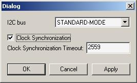
In the "I2C bus" drop list you can choose the frequency of the I2C bus. It can have one of the following values:
Fast mode (400 kHz);
Standard mode (100 kHz);
Any value in the range 2 kHz – 83 kHz.
Select the “Clock Synchronization” check-box to turn on the clock synchronization (Clock Stretching). This option is only available for the frequencies below or equal to "Standard-mode" (<=100 kHz). In "Fast-mode" this option is unavailable.
The “Clock Synchronization Timeout” field allows to change the clock stretching timeout value (integer number from 1 to 65535). Clock synchronization (clock stretching) timeout value specified as multiple of 100 microseconds.
"I2C Bridge Devices" Bar
The "I2C Bridge Devices" Bar (Figure 2.4, “"I2C Bridge Devices" Bar”) includes the following buttons:
Figure 2.4. "I2C Bridge Devices" Bar
“Open Device” button
Click to choose one of the U2C-12 adapters connected to the PC. If only one U2C-12 adapter is connected, it becomes selected automatically. If several U2C-12 adapters are connected to the same PC, the “Device Open” dialog window will appear (Figure 2.5, ““Open Device” dialog window”). You can use the device serial number to open the specific adapter.
Figure 2.5. “Open Device” dialog window
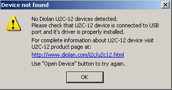
If there are no connected U2C-12 adapters, the “Device not found” message (Figure 2.6, ““Device not found” message”) will be displayed.
Figure 2.6. “Device not found” message
When Control Panel application is started it opens the device. The “Open Device” button can be used by user for switching to the new adapter after it was connected.
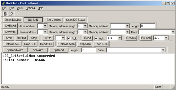
- “Get S/N” button
Each of the U2C-12 adapters has the unique serial number. To view the serial number of your U2C-12 adapter you can use the “Get S/N” button. The U2C-12 adapter serial number is displayed in log field (Figure 2.7, “Information about serial number of U2C-12 adapter”).
Figure 2.7. Information about serial number of U2C-12 adapter
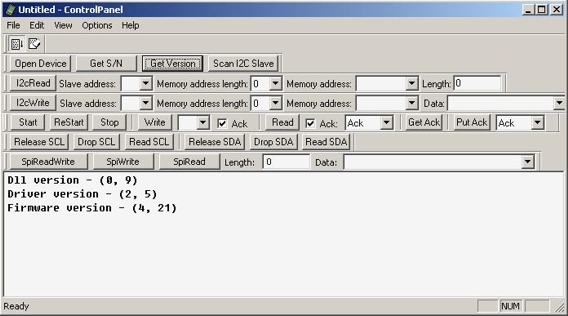
- “Get Version” button
The “Get Version” button displays U2C-12 adapter software version in the log field. (Figure 2.8, “Information about U2C-12 adapter software and firmware version”).
Figure 2.8. Information about U2C-12 adapter software and firmware version
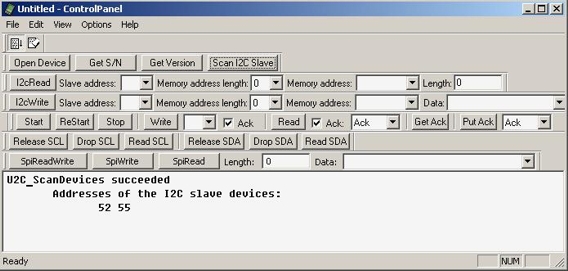
“Scan I2C Slave” button
The “Scan I2C Slave” button scans the I2C slave device addresses currently occupied by the I2C slave devices which are connected to the U2C-12 adapter. The I2C slave device addresses are displayed in the log field in hexadecimal format (Figure 2.9, “The I2C slave device addresses”). They are also added to “Slave address” drop list of “I2C Write” and “I2C Read” bars. U2C-12 adapter supports 7-bit addressing format.
Figure 2.9. The I2C slave device addresses
"I2C Read" Bar
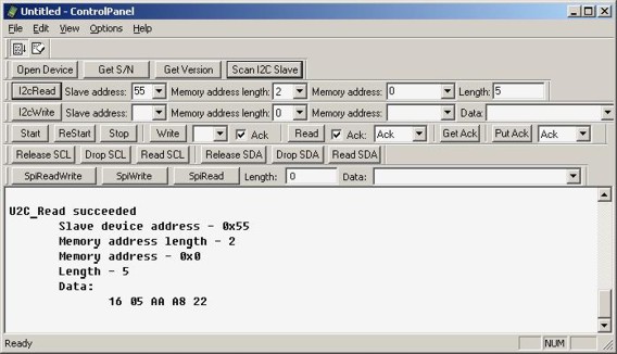
I2C Read” Bar (Figure 2.10, ““I2C Read” Bar”) is used to read data from I2C slave device.
Figure 2.10. “I2C Read” Bar
Each I2C slave device has its own 7-bit address. Enter it in the “Slave address” field. The I2C slave device address is an integer hexadecimal number in the range from 0 to 7F. Click the “Scan I2C Slave” button (Figure 2.9, “The I2C slave device addresses”) to get the list of addresses currently occupied by I2C slave devices.
Some I2C slave devices (e.g. I2C EEPROMs) have their own internal addressing. If your I2C slave device supports internal addressing, you can enter the internal address in the "Memory address" field and the address length (in bytes) in the “Memory address length” field. If your I2C slave device doesn’t support the internal addressing, enter “0” in the “Memory address length” field. Memory address length depends on the I2C slave device type. If the memory address length value is incorrect, you will get the wrong data.
Possible memory address values for the particular memory address length are listed in table.
| Memory address length value | Memory address values range |
|---|---|
| 1 | 0-FF |
| 2 | 0-FFFFFF |
| 4 | 0-FFFFFFFF |
Enter the number of bytes to be read from the I2C slave device into the “Length” field (integer decimal value from 1 to 256).
After you have entered the correct values, press the “I2c Read” button to read the data from the I2C slave device. You can see the result in the log field (Figure 2.11, “The result of the data reading from the I2C slave device”).
Figure 2.11. The result of the data reading from the I2C slave device
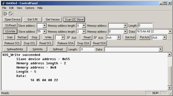
"I2C Write" Bar
Figure 2.12. The "I2C Write" Bar
Each I2C slave device has its own 7-bit address. Enter it in the “Slave address” field. The I2C slave device address is an integer hexadecimal number in the range from 0 to 7F. Click the “Scan I2C Slave” button (Figure 2.9, “The I2C slave device addresses”) to get the list of addresses currently occupied by the I2C slave devices.
Some I2C slave devices (e.g. I2C EEPROMs) have their own internal addressing. If your I2C slave device supports internal addressing, you can enter the internal address in the "Memory address" field and the address length (in bytes) in the “Memory address length” field. If your I2C slave device doesn’t support the internal addressing, enter “0” in the “Memory address length” field. Memory address length depends on the I2C slave device type. If the memory address length value is incorrect, you will get the wrong data.
The possible memory address values for the particular memory address length are listed in table.
| Memory address length value | Memory address values range |
|---|---|
| 1 | 0-FF |
| 2 | 0-FFFFFF |
| 4 | 0-FFFFFFFF |
In the “Data” field you can enter the data to be sent to the I2C slave device. You can type hexadecimal values (from 0 to FF) to the field. To enter more then one value separate them by space.
After you have entered the correct values press the “I2с Write” button to send the data to the I2C slave device. You can see the result in the log field Figure 2.13, “The result of data writing into the I2C slave device”.
Figure 2.13. The result of data writing into the I2C slave device
"I2C Bus Level" Bar
The "I2C Bus Level" Bar (Figure 2.19, “"I2C Bus Level" Bar”) allows to work with the I2C slave devices on the bus level (SDA and SCL lines). The bar buttons make it possible to read and write the data by controlling the bus lines.
Figure 2.19. "I2C Bus Level" Bar
The "Release SCL" button releases the SCL line of the I2C bus. If the SCL line is not pulled down by I2C slave device, it will get high.
The "Drop SCL" pulls down the I2C bus SCL line.
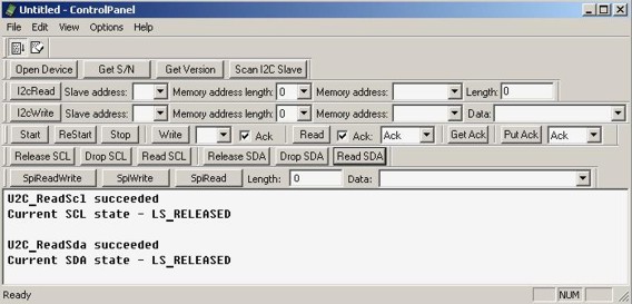
The "Read SCL" button checks the current state of the I2C bus SCL line.
The "Release SDA" button releases the SDA line of the I2C bus. If the line is not pulled down by I2C slave device, it will get high.
The "Drop SDA" button pulls down the I2C bus SDA line.
The "Read SDA" button checks the current state of the I2C bus SDA line.
For instance, by consiquent pressing the "Read SCL" and "Read SDA" buttons (on condition that the I2C bus is released) the messages informing that the both lines are released will be displayed in the log field (Figure 2.20, “Reading the SDA/SCL lines”).
Figure 2.20. Reading the SDA/SCL lines
"I2C Low Level" Bar
The “I2C Low Level” bar (Figure 2.14, “"I2C Low Level" Bar”) allows to work with the I2C slave devices on the low level.
Figure 2.14. "I2C Low Level" Bar
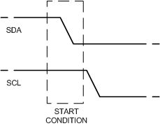
The “Start” button generates the START condition on the I2C bus, i.e. a HIGH to LOW transition of the SDA line while the SCL line is HIGH. The START condition (Figure 2.15, “The START condition”) indicates the beginning of the data exchange operation.
Figure 2.15. The START condition
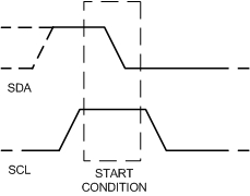
The “ReStart” button generates the repeated START condition (Figure 2.16, “The repeated START condition”). It is used to allow combined write/read operations without releasing the bus and interrupting the operation.
Figure 2.16. The repeated START condition
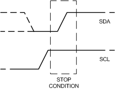
The “Stop” button generates the STOP condition (Figure 2.17, “The STOP condition”) on the I2C bus, i.e. a HIGH to LOW transition of the SDA line while the SCL line is HIGH. The bus is considered to be free after the STOP condition.
Figure 2.17. The STOP condition
The “Write” button transmits the data byte from I2C master to I2C slave device. Enter the transmitted value into the “Write” field (integer hexadecimal value from 0 to FF).
If the "Ack" (Write) check-box is selected, acknowledge will be requested from the I2C slave device after the data byte transmission.
If the "Ack" (Write) check-box is not selected, acknowledge will not be requested. It may lead to the data loss. You can still press the "Get Ack" button to request acknowledge.
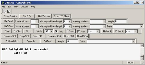
The “Read” button transmits the data byte from I2C slave to I2C master device. The information about the byte data requested is desplayed in the log field (Figure 2.18, “The information about the byte data reading with the "Ack" signal”).
Figure 2.18. The information about the byte data reading with the "Ack" signal
If the "Ack" (read) check-box is selected, acknowledge ("Ack" or "No Ack" depends on the value of “Put Ack” drop list) will be generated.
If "Ack" (read) check-box is not selected, acknowledge will not be generated. You can still press the “Put Ack” button to generate acknowledge. Without acknowledge the further data reading can be incorrect.
The “Get Ack” button requests acknowledge from the I2C slave device.
The “Put Ack” button generates acknowledge on the I2C bus ("Ack” or “No Ack” depends on the value of “Put Ack” drop list).
"SPI Bus Configuration" Dialog Window
In the “SPI Bus Configuration” dialog window (Figure 2.3, ““Spi Bus Configuration” dialog window”) you can change the settings of the SPI bus. To open this dialog window select "Options/Spi Configuration".
Figure 2.3. “Spi Bus Configuration” dialog window
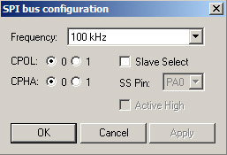
In the "Frequency" drop list you can choose the clock frequency of the SPI bus. The frequency should be less than or equal to the maximum frequency the SPI slave device supports. It can have value up to 200 kHz.
In addition to setting the clock frequency, the SPI master device must also configure the clock polarity ("CPOL") and clock phase ("CPHA").
Clock phase and polarity should be identical for the SPI master device and the communicating SPI slave device. In some cases, the phase and polarity are changed between transmissions to allow a SPI master device to communicate with peripheral SPI slaves having different requirements.
The CPOL clock polarity control bit specifies an active high or low clock. The CPHA clock phase control bit selects one of two fundamentally different transmission formats:
CPHA=0. The first edge on the SCK line is used to clock the first data bit of slave into the SPI master and the first data bit of SPI master into the SPI slave. In some peripherals, the first bit of the slave's data is available at the slave data out pin as soon as the slave is selected. In this format, the first SCK edge is not issued until a half cycle into the 8-cycle transfer operation. The first edge of SCK is delayed a half cycle by clearing the CPHA bit.
CPHA=1. Some peripherals require the first SCK edge before the first data bit becomes available at the data out pin; the second edge clocks data into the system. In this format, the first SCK edge is issued by setting the CPHA bit at the beginning of the 8-cycle transfer operation.
Select the "Slave Select" check-box if the connected SPI slave device supports the SPI slave selection. The "SS Pin" drop list allows to choose the slave select pin of U2C-12 adapter to which SPI slave device is connected. The SPI master device must select only one SPI slave device at a time.
The "Active High" check-box allows to determine the active state of the Slave Select signal (state during the SPI transfer). When the slave select line is active, the SPI master device can operate with the SPI slave device. If the "Active high" check-box is not checked - Slave Select pin value will be changed from logical "1" to logical "0" before SPI transaction and returned back to logical "1" after the data is transmitted. If the "Active high" check-box is checked - Slave Select pin value will be changed from logical "0" to logical "1" before SPI transaction and returned back to logical "0" after the data is transmitted. You can use this mode while working with the Microwire bus.
"SPI Bus" Bar
The "SPI Bus Level" Bar (Figure 2.21, “The "SPI Bus" bar”) allows to read and write the data over the SPI bus.
Figure 2.21. The "SPI Bus" bar
The "Spi ReadWrite" button shifts out (writes) and in (reads) a stream of up to 256 bytes to/from the SPI slave device. The shift operation is occurred in a full duplex data transmission mode.
The "Spi Write" button shifts out (writes) a stream of up to 256 bytes to the SPI slave device.
The "Spi Read" button shifts in (reads) a stream of up to 256 bytes from the SPI slave device.
The "Length" field allows you to enter the number of bytes to be shifted. Maximum value is 256.
The "Data" field allows you to enter the data to be shifted. You can type hexadecimal values (from 0 to FF) to the field. To enter more then one value separate them by space.
API Documentation
U2C_CloseDevice()
U2C_RESULT U2C_CloseDevice(
      HANDLE hDevice
);
The U2C_CloseDevice() function closes the open device handle.
Parameters:
- hDevice
- Handle to the U2C-12 device to close.
Return values:
U2C_SUCCESS
The device referenced by hDevice handle was successfully closed.
U2C_HARDWARE_NOT_FOUND
U2C-12 device referenced by hDevice handle was not found.
U2C_DropScl()
U2C_RESULT U2C_DropScl(
      HANDLE hDevice
);
The U2C_DropScl() function pulls down the I2C bus SCL line.
Parameters:
- hDevice
Handle to the U2C-12 device.
Return values:
U2C_SUCCESS
The SCL line was successfully dropped.
U2C_HARDWARE_NOT_FOUND
U2C-12 device referenced by hDevice handle was not found.
U2C_DropSda()
U2C_RESULT U2C_DropSda(
      HANDLE hDevice
);
The U2C_DropSda() function pulls down the I2C bus SDA line.
Parameters:
- hDevice
Handle to the U2C-12 device.
Return values:
U2C_SUCCESS
The SDA line was successfully dropped.
U2C_HARDWARE_NOT_FOUND
U2C-12 device referenced by hDevice handle was not found.
U2C_GetAck()
U2C_RESULT U2C_GetAck(
      HANDLE hDevice,
);
The U2C_GetAck() function checks for acknowledge from I2C slave device. This function does not finish the I2C bus transaction after transmission, so at the end of I2C transaction U2C_Stop() function has to be called.
Parameters:
- hDevice
Handle to the U2C-12 device.
Return values:
U2C_SUCCESS
I2C slave device provided acknowledge.
U2C_HARDWARE_NOT_FOUND
U2C-12 device referenced by hDevice handle was not found.
U2C_NO_ACK
I2C slave device did not provide acknowledge.
U2C_GetByte()
U2C_RESULT U2C_GetByte(
      HANDLE hDevice,
      BYTE* pData
);
The U2C_GetByte() function shifts in (reads) a single byte from I2C bus. It assumes that the bus is available, Start Condition has been previously generated and the slave device has been properly addressed. This function doesn't generate acknowledge, so you must call the U2C_PutAck() function or use U2C_GetByteWithAck() instead ofU2C_GetByte() function. This function can be called several times to implement custom I2C-like protocol. The function does not finish I2C bus transaction after transmission, so at the end of I2C transaction U2C_Stop() function has to be called.
Parameters:
- hDevice
Handle to the U2C-12 device.
- pData
A pointer to byte to be filled with data read from the I2C bus.
Return values:
U2C_SUCCESS
Byte was successfully read from I2C bus.
U2C_HARDWARE_NOT_FOUND
U2C-12 device referenced by hDevice handle was not found.
U2C_GetByteWithAck()
U2C_RESULT U2C_GetByteWithAck(
      HANDLE hDevice,
      BYTE* pData,
      BOOL bAck
);
The U2C_GetByteWithAck() function shifts in (reads) a single byte from the I2C bus and then generates acknowledge or not-acknowledge condition according to the value passed in bAck parameter. It assumes that the bus is available, Start Condition has been previously generated and the slave device has been properly addressed. This function can be called several times to implement custom I2C-like protocol. The function does not finish the I2C bus transaction after transmission, so at the end of I2C transaction U2C_Stop() function has to be called.
Parameters:
- hDevice
Handle to the U2C-12 device.
- pData
A pointer to byte to be filled with data read from the I2C bus.
- bAck
This parameter determines if acknowledge should be generated after the byte is transmitted. If bAck is TRUE - acknowledge will be generated, if bAck is FALSE - non-acknowledge will be generated.
Return values:
U2C_SUCCESS
Byte was successfully read from I2C bus.
U2C_HARDWARE_NOT_FOUND
U2C-12 device referenced by hDevice handle was not found.
U2C_GetClockSynch()
U2C_RESULT U2C_SetClockSynch(
      HANDLE hDevice,
      BOOL* pEnable
);
The U2C_GetClockSynch() function retrieves I2C bus clock synchronization settings.
Clock synchronization (clock stretching) is used in situations where an I2C slave is not able to co-operate with the clock speed provided by the U2C-12 I2C master and needs to slow down the I2C bus. I2C slave holds down the SCL line low and in this way signals the I2C master about a wait state. If I2C bus clock synchronization is enabled, U2C-12 device will wait until I2C slave device releases the SCL line.
![[Warning]](http://www.diolan.com/assets/warning-3a4e1497101f412993cf4fafbf3fe5e2.png) | Warning |
|---|---|
| I 2 C bus clock synchronization (clock stretching) is implemented for I 2 C bus frequencies up to 100kHz. See U2C_SetI2cFreq() to learn how to change I 2 C bus frequency. |
Parameters:
- hDevice
Handle to the U2C-12 device.
- pEnable
Clock synchronization (clock stretching) enable/disable value:
- 1 corresponds to I 2 C bus clock synchronization enabled.
- 0 corresponds to I 2 C bus clock synchronization disabled.
Return values:
U2C_SUCCESS
The I2C bus clock synchronization value was successfully retrieved.
U2C_HARDWARE_NOT_FOUND
U2C-12 device referenced by hDevice handle was not found.
U2C_GetClockSynchTimeout()
U2C_RESULT U2C_GetClockSynchTimeout(
      HANDLE hDevice,
      WORD* pTimeout
);
The U2C_GetClockSynchTimeout() function retrieves timeout value for I2C bus clock synchronization.
Clock synchronization (clock stretching) is used in situations where I2C slave device is not able to cooperate on the clock speed provided by the U2C-12 I2C master and needs to slow down the I2C bus. I2C slave holds down the SCL line low and in that way signals the I2C master about a wait state. To avoid waiting deadlock (if some problem occurs with I2C slave device) timeout value was introduced into U2C-12 I2C interface. If I2C slave device doesn't release the clock within the given timeout interval, U2C-12 adapter returns the U2C_I2C_CLOCK_SYNCH_TIMEOUT error value.
| Warning |
|---|---|
| I 2 C bus clock synchronization (clock stretching) is implemented for I 2 C bus frequencies up to 100kHz. See U2C_SetI2cFreq() to learn how to change I 2 C bus frequency. |
Parameters:
- hDevice
Handle to the U2C-12 device.
- pTimeout
Pointer to variable to be filled with clock synchronization timeout value.
Return values:
U2C_SUCCESS
The I2C bus clock synchronization timeout value was successfully retrieved.
U2C_HARDWARE_NOT_FOUND
U2C-12 device referenced by hDevice handle was not found.
U2C_GetDeviceCount()
BYTE U2C_GetDeviceCount();
The U2C_GetDeviceCount() function checks how many U2C-12 devices are currently attached.
Returns:
The function returns the number of the U2C-12 devices detected on current computer.
U2C_GetDllVersion()
U2C_VERSION_INFO U2C_GetDllVersion();
The U2C_GetDllVersion() function retrieves the version of the I2CBrdg.dll dynamic link library or shared library for Linux.
Returns:
U2C_VERSION_INFO structure containing I2CBrdg.dll dynamic link library version number.
U2C_GetDriverVersion()
U2C_RESULT U2C_GetDriverVersion(
      HANDLE hDevice,
      PU2C_VESION_INFO pVersion
);
The U2C_GetDriverVersion() function retrieves the version of the driver used to communicate with U2C-12 device.
Parameters:
- hDevice
- Handle to the U2C-12 device to obtain the version of the driver used to communicate with.
- pVersion
- Pointer to a U2C_VERSION_INFO structure to be filled with the driver version number.
Return values:
U2C_SUCCESS
The driver version was successfully retrieved.
U2C_HARDWARE_NOT_FOUND
U2C-12 device referenced by hDevice handle was not found.
U2C_GetFirmwareVersion()
U2C_RESULT U2C_GetFirmwareVersion(
      HANDLE hDevice,
      PU2C_VESION_INFO pVersion
);
The U2C_GetFirmwareVersion() function retrieves the version of the firmware currently loaded into the U2C-12 device referenced by hDevice handle.
Parameters:
- hDevice
- Handle to the U2C-12 device to obtain firmware version from.
- pVersion
- Pointer to a U2C_VERSION_INFO structure to be filled with the firmware version number.
Return values:
U2C_SUCCESS
The firmware version was successfully retrieved.
U2C_HARDWARE_NOT_FOUND
U2C-12 device referenced by hDevice handle was not found.
U2C_GetI2cFreq()
U2C_RESULT U2C_GetI2cFreq(
      HANDLE hDevice,
      BYTE* pFrequency
);
The U2C_GetI2cFreq() function obtains I2C bus frequency.
Parameters:
- hDevice
Handle to the U2C-12 device.
- pFrequency
A pointer to byte to be filled with current I2C bus frequency, where:
For convenience following constants were introduced:- 0 corresponds to I 2 C bus fast mode (400 kHz).
- 1 corresponds to I 2 C bus standard mode (100 kHz).
- 1+n corresponds to clock period of I 2 C bus equal to 10 + 2*n uS.
U2C_I2C_FREQ_FAST I2C bus fast mode (400 kHz) U2C_I2C_FREQ_STD I2C bus standard mode (100 kHz) U2C_I2C_FREQ_83KHZ 83 kHz U2C_I2C_FREQ_71KHZ 71 kHz U2C_I2C_FREQ_62KHZ 62 kHz U2C_I2C_FREQ_50KHZ 50 kHz U2C_I2C_FREQ_25KHZ 25 kHz U2C_I2C_FREQ_10KHZ 10 kHz U2C_I2C_FREQ_5KHZ 5 kHz U2C_I2C_FREQ_2KHZ 2 kHz
Return values:
U2C_SUCCESS
The I2C bus frequency value was successfully retrieved.
U2C_HARDWARE_NOT_FOUND
U2C-12 device referenced by hDevice handle was not found.
U2C_GetIoDirection()
U2C_RESULT U2C_GetIoDirection(
      HANDLE hDevice,
      ULONG* pValue
);
The U2C_GetIoDirection() function obtains current input/output direction of the GPIO port pins.
Parameters:
- hDevice
Handle to the U2C-12 device.
- pValue
A pointer to unsigned long to be filled with the direction of the GPIO pins. pValue is treated as unsigned long 0xXXCCBBAA, where CC, BB and AA correspond to the C, B and A port pins:
Bit set to 1 indicates configuration of the corresponding pin as output. Bit set to 0 indicates configuration of the corresponding pin as input.- AA bits 7..0 correspond to Port A pins 7..0
- BB bits 7..0 correspond to Port B pins 7..0
- CC bits 7..0 correspond to Port C pins 7..0
- XX bits 7..0 reserved
Return values:
U2C_SUCCESS
The GPIO pins direction was successfully read.
U2C_HARDWARE_NOT_FOUND
U2C-12 device referenced by hDevice handle was not found.
U2C_GetSerialNum()
U2C_RESULT U2C_GetSerialNum(
      HANDLE hDevice,
      long* pSerialNum
);
The U2C_GetSerialNum() function retrieves the Serial Number of the current device. This is unique Serial Number. It can be used to identify device when you are using a number of U2C-12 devices simultaneously.
Parameters:
- hDevice
- Handle to the U2C-12 device to retrieve the Serial Number from. The device has to be opened first, using U2C_OpenDevice() or U2C_OpenDeviceBySerialNum()function.
- pSerialNum
- Pointer to a long integer variable to be filled with the device Serial Number.
Return values:
U2C_SUCCESS
Serial Number was successfully obtained.
U2C_HARDWARE_NOT_FOUND
U2C-12 device referenced by hDevice handle was not found.
U2C_GetSingleIoDirection()
U2C_RESULT U2C_GetSingleIoDirection(
      HANDLE hDevice,
      ULONG IoNumber,
      BOOL* pbOutput
);
The U2C_GetSingleIoDirection() function obtains input/output direction of the specified GPIO pin.
Parameters:
- hDevice
Handle to the U2C-12 device.
- IoNumber
The number of the GPIO pin to obtain direction:
- Numbers 0..7 correspond to Port A pins 0..7
- Numbers 8..15 correspond to Port B pins 0..7
- Number 16..23 correspond to Port C pins 0..7
- pbOutput
A pointer to the boolean to be filled with the direction of the GPIO pin:
- *pbOutput = TRUE indicates that the GPIO pin is configured for output
- *pbOutput = FALSE indicates that the GPIO pin is configured for input
Return values:
U2C_SUCCESS
The GPIO pin direction was successfully read.
U2C_HARDWARE_NOT_FOUND
U2C-12 device referenced by hDevice handle was not found.
U2C_BAD_PARAMETER
IoNumber is out of range.
U2C_IoRead()
U2C_RESULT U2C_IoRead(
      HANDLE hDevice,
      ULONG* pValue
);
The U2C_IoRead() function obtains the value of the GPIO port pins.
Parameters:
- hDevice
Handle to the U2C-12 device.
- pValue
A pointer to unsigned long to be filled with the value of the GPIO pins. pValue is treated as unsigned long 0xXXCCBBAA, where CC, BB and AA correspond to the C, B and A port pins:
- AA bits 7..0 correspond to Port A pins 7..0
- BB bits 7..0 correspond to Port B pins 7..0
- CC bits 7..0 correspond to Port C pins 7..0
- XX bits 7..0 reserved
Return values:
U2C_SUCCESS
The GPIO pins state was successfully read.
U2C_HARDWARE_NOT_FOUND
U2C-12 device referenced by hDevice handle was not found.
U2C_IoWrite()
U2C_RESULT U2C_IoWrite(
      HANDLE hDevice,
      ULONG Value,
      ULONG Mask
);
The U2C_IoWrite() sets the output value of the GPIO port pins. Pins have to be configured as output using the U2C_SetIoDirection() function first.
Parameters:
- hDevice
Handle to the U2C-12 device.
- Value
An unsigned long value specifying the value to be set to the GPIO pins. Value is treated as unsigned long 0xXXCCBBAA, where CC, BB and AA correspond to the C, B and A port pins:
- AA bits 7..0 correspond to Port A pins 7..0
- BB bits 7..0 correspond to Port B pins 7..0
- CC bits 7..0 correspond to Port C pins 7..0
- XX bits 7..0 reserved
- Mask
An unsigned long value specifying the data mask to use when modifying the GPIO pins output value. The mask value allows modification of the desired pins only, leaving rest of the pins unchanged. The bit mapping for Mask parameter is exactly the same as for Value parameter. Only value of the pins with mask bit set to 1 will be changed.
Return values:
U2C_SUCCESS
The GPIO pins output value was successfully modified.
U2C_HARDWARE_NOT_FOUND
U2C-12 device referenced by hDevice handle was not found.
U2C_IsHandleValid()
U2C_RESULT U2C_IsHandleValid(
      HANDLE hDevice
);
The U2C_IsHandleValid() function checks whether the device referenced by hDevice handle is currently attached to the USB and can be used by SW.
Parameters:
- hDevice
- Handle to the U2C-12 device that will be checked.
Return values:
U2C_SUCCESS
The device referenced by hDevice handle is present.
U2C_HARDWARE_NOT_FOUND
U2C-12 device referenced by hDevice handle was not found.
U2C_OpenDevice()
HANDLE U2C_OpenDevice(
      BYTE nDevice
);
The U2C_OpenDevice() function opens the U2C-12 device.
Parameters:
- nDevice
- The device number to open.
Returns:
If function succeeds, the return value is a valid handle to the specified device. If function fails, the return value is INVALID_HANDLE_VALUE. This can happen if the specified device is not present.
U2C_OpenDeviceBySerialNum()
HANDLE U2C_OpenDeviceBySerialNum(
      long nSerialNum
);
The U2C_OpenDeviceBySerialNum() function opens the U2C-12 device with specified Serial Number. This is unique Serial Number. It can be used to identify device when you are using a number of U2C-12 devices simultaneously.
Parameters:
- nSerialNum
- The Serial Number of the device to open.
Returns:
If function succeeds, the return value is a valid handle to the specified device. If function fails, the return value is INVALID_HANDLE_VALUE. This can happen if the device with specified Serial Number is not present.
U2C_PutAck()
U2C_RESULT U2C_PutAck(
      HANDLE hDevice,
      BOOL bAck
);
The U2C_PutAck() function generates acknowledge or not-acknowledge condition according to the value passed in bAck parameter. This function does not finish the I2C bus transaction after transmission, so at the end of I2C transaction U2C_Stop() function has to be called.
Parameters:
- hDevice
Handle to the U2C-12 device.
- bAck
This parameter determines whether acknowledge or non-acknowledge should be generated. If bAck is TRUE - acknowledge will be generated, if bAck is FALSE - non-acknowledge will be generated.
Return values:
U2C_SUCCESS
Acknowledge / non-acknowledge condition was successfully generated.
U2C_HARDWARE_NOT_FOUND
U2C-12 device referenced by hDevice handle was not found.
U2C_PutByte()
U2C_RESULT U2C_PutByte(
      HANDLE hDevice,
      BYTE Data
);
The U2C_PutByte() function shifts out (transmits) a single byte to I2C bus. It assumes that the bus is available and Start Condition has been generated first. This function doesn't check acknowledge from I2C slave device, so you must call the U2C_GetAck() function to check acknowledge or to use U2C_PutByteWithAck() instead ofU2C_PutByte() function. This function can be called several times to implement custom I2C-like protocol. The function does not finish I2C bus transaction after transmission, so at the end of I2C transaction U2C_Stop() function has to be called.
Parameters:
- hDevice
Handle to the U2C-12 device.
- Data
Byte value to be transmitted to the I2C bus.
Return values:
U2C_SUCCESS
Byte was successfully transmitted to the I2C bus.
U2C_HARDWARE_NOT_FOUND
U2C-12 device referenced by hDevice handle was not found.
U2C_PutByteWithAck()
U2C_RESULT U2C_PutByteWithAck(
      HANDLE hDevice,
      BYTE Data
);
The U2C_PutByteWithAck() function shifts out (transmits) a single byte to I2C bus and checks for acknowledge from I2C slave device. It assumes that the bus is available and Start Condition has been generated first. This function can be called several times to implement custom I2C-like protocol. The function does not finish the I2C bus transaction after transmission, so at the end of I2C transaction U2C_Stop() function has to be called.
Parameters:
- hDevice
Handle to the U2C-12 device.
- Data
Byte value to be transmitted to the I2C bus.
Return values:
U2C_SUCCESS
Byte was successfully transmitted to the I2C bus and I2C slave device provided acknowledge.
U2C_HARDWARE_NOT_FOUND
U2C-12 device referenced by hDevice handle was not found.
U2C_NO_ACK
I2C slave device did not acknowledge the transmitted byte.
U2C_RW_Pack()
U2C_RESULT U2C_RW_Pack(
      HANDLE hDevice,
      PU2C_TRANSACTION_PACK pTransaction,
      int count
);
| Warning |
|---|---|
| This function is implemented only for Linux and Mac versions of the library. |
The U2C_RW_Pack() function executes a list (pack) of I2C read/write transactions. All transactions are sent to U2C-12 device in a single USB transfer block.U2C_RW_Pack() waits until all I2C transactions are completed and returns each transaction result code in pTransaction[i].rc element. I2C transactions are performed sequentially in the same order as they are in the pack. Take care to pack correct sequence of the transactions. For instance attempt to read/write after write to I2C EEPROM may timeout because of the internal EEPROM write cycle.
Parameters:
- hDevice
Handle to the U2C-12 device.
- pTransaction
List of I2C transactions.
- count
Number of I2C transactions in the pTransaction list.
Return values:
U2C_SUCCESS
Operation was successfully completed and pList is filled with valid data.
U2C_HARDWARE_NOT_FOUND
U2C-12 device referenced by hDevice handle was not found.
U2C_BAD_PARAMETER
I2C transactions list is too big.
U2C_Read()
U2C_RESULT U2C_Read(
      HANDLE hDevice,
      PU2C_TRANSACTION pTransaction
);
The U2C_Read function() reads up to 256 bytes from the I2C slave device.
Parameters:
- hDevice
Handle to the U2C-12 device.
- pTransaction
Pointer to the U2C_TRANSACTION structure to be used during the I2C read transaction. Before calling the function this structure has to be partially filled:
After successful completion of the read operation Buffer member of the structure will be filled with data read from I2C slave device.- nSlaveDeviceAddress - must contain the I 2 C slave device address.
- nMemoryAddressLength - must contain the internal address length (in bytes from 0 up to 4). If nMemoryAddressLength is equal to 0, no address will be sent to device and repeated I 2 C start condition won't be generated.
- MemoryAddress - must contain the internal I 2 C slave device address.
- nBufferLength - must contain the number of bytes to be read from the I 2 C slave device.
Return values:
U2C_SUCCESS
The data was successfully read.
U2C_HARDWARE_NOT_FOUND
U2C-12 device referenced by hDevice handle was not found.
U2C_SLAVE_OPENNING_FOR_WRITE_FAILED
I2C slave device did not acknowledge write slave address.
U2C_SLAVE_OPENNING_FOR_READ_FAILED
I2C slave device did not acknowledge read slave address.
U2C_SENDING_MEMORY_ADDRESS_FAILED
I2C slave device did not acknowledge internal address.
U2C_ReadScl()
U2C_RESULT U2C_ReadScl(
      HANDLE hDevice,
      U2C_LINE_STATE* pState
);
The U2C_ReadScl() function checks the current state of the I2C bus SCL line.
Parameters:
- hDevice
Handle to the U2C-12 device.
- pState
Pointer to the location to be filled with the SCL line state:
- LS_RELEASED - SCL line is released (high).
- LS_DROPPED_BY_I2C_BRIDGE - U2C-12 device has pulled down the SCL line.
- LS_DROPPED_BY_SLAVE - I 2 C slave device has pulled down the SCL line.
Return values:
U2C_SUCCESS
The SCL line state was successfully read.
U2C_HARDWARE_NOT_FOUND
U2C-12 device referenced by hDevice handle was not found.
U2C_ReadSda()
U2C_RESULT U2C_ReadSda(
      HANDLE hDevice,
      U2C_LINE_STATE* pState
);
The U2C_ReadSda() function checks the current state of the I2C bus SDA line.
Parameters:
- hDevice
Handle to the U2C-12 device.
- pState
Pointer to the location to be filled with the SDA line state:
- LS_RELEASED - SDA line is released (high).
- LS_DROPPED_BY_I2C_BRIDGE - U2C-12 device has pulled down the SDA line.
- LS_DROPPED_BY_SLAVE - I 2 C slave device has pulled down the SDA line.
Return values:
U2C_SUCCESS
The SDA line state was successfully read.
U2C_HARDWARE_NOT_FOUND
U2C-12 device referenced by hDevice handle was not found.
U2C_ReleaseScl()
U2C_RESULT U2C_ReleaseScl(
      HANDLE hDevice
);
The U2C_ReleaseScl() function releases the SCL line of the I2C bus. If the SCL line is not pulled down by I2C slave device, it will get high.
Parameters:
- hDevice
Handle to the U2C-12 device.
Return values:
U2C_SUCCESS
The SCL line was successfully released.
U2C_HARDWARE_NOT_FOUND
U2C-12 device referenced by hDevice handle was not found.
U2C_ReleaseSda()
U2C_RESULT U2C_ReleaseSda(
      HANDLE hDevice
);
The U2C_ReleaseSda() function releases the SDA line of the I2C bus. If the line is not pulled down by I2C slave device, it will get high.
Parameters:
- hDevice
Handle to the U2C-12 device.
Return values:
U2C_SUCCESS
The SDA line was successfully released.
U2C_HARDWARE_NOT_FOUND
U2C-12 device referenced by hDevice handle was not found.
U2C_RepeatedStart()
U2C_RESULT U2C_RepeatedStart(
      HANDLE hDevice
);
The U2C_RepeatedStart() function generates repeated start condition on the I2C bus.
Parameters:
- hDevice
Handle to the U2C-12 device.
Return values:
U2C_SUCCESS
Repeated start condition was successfully generated.
U2C_HARDWARE_NOT_FOUND
U2C-12 device referenced by hDevice handle was not found.
U2C_ScanDevices()
U2C_RESULT U2C_ScanDevices(
      HANDLE hDevice,
      PU2C_SLAVE_ADDR_LIST pList
);
The U2C_ScanDevices() function scans slave device addresses currently occupied by I2C slave devices connected to the I2C bus.
Parameters:
- hDevice
Handle to the U2C-12 device.
- pList
Pointer to the U2C_SLAVE_ADDR_LIST structure to be filled with slave device addresses. If function succeed nDeviceNumber member contains the number of the valid addresses in List array.
Return values:
U2C_SUCCESS
Operation was successfully completed and pList is filled with valid data.
U2C_HARDWARE_NOT_FOUND
U2C-12 device referenced by hDevice handle was not found.
U2C_SetClockSynch()
U2C_RESULT U2C_SetClockSynch(
      HANDLE hDevice,
      BOOL Enable
);
The U2C_SetClockSynch() function enables I2C bus clock synchronization.
Clock synchronization (clock stretching) is used in situations where an I2C slave is not able to co-operate with the clock speed provided by the U2C-12 I2C master and needs to slow down the I2C bus. I2C slave holds down the SCL line low and in this way signals the I2C master about a wait state. If I2C bus clock synchronization is enabled, U2C-12 device will wait until I2C slave device releases the SCL line.
| Warning |
|---|---|
| I 2 C bus clock synchronization (clock stretching) is implemented for I 2 C bus frequencies up to 100kHz. See U2C_SetI2cFreq() to learn how to change I 2 C bus frequency. |
Parameters:
- hDevice
Handle to the U2C-12 device.
- Enable
Clock synchronization (clock stretching) enable/disable value:
- 1 corresponds to I 2 C bus clock synchronization enabled.
- 0 corresponds to I 2 C bus clock synchronization disabled.
Return values:
U2C_SUCCESS
The I2C bus clock synchronization value was successfully set.
U2C_HARDWARE_NOT_FOUND
U2C-12 device referenced by hDevice handle was not found.
U2C_SetClockSynchTimeout()
U2C_RESULT U2C_SetClockSynchTimeout(
      HANDLE hDevice,
      WORD Timeout
);
The U2C_SetClockSynchTimeout() function configures timeout value for I2C bus clock synchronization.
Clock synchronization (clock stretching) is used in situations where I2C slave device is not able to cooperate on the clock speed provided by the U2C-12 I2C master and needs to slow down the I2C bus. I2C slave holds down the SCL line low and in that way signals the I2C master about a wait state. To avoid waiting deadlock (if some problem occurs with I2C slave device) timeout value was introduced into U2C-12 I2C interface. If I2C slave device doesn't release the clock within the given timeout interval, U2C-12 adapter returns the U2C_I2C_CLOCK_SYNCH_TIMEOUT error value.
The U2C_SetClockSynchTimeout() function doesn't enables or disables clock stretching functionality. It only changes the clock stretching timeout value. Clock stretching should be enabled with U2C_SetClockSynch() function.
| Warning |
|---|---|
| I 2 C bus clock synchronization (clock stretching) is implemented for I 2 C bus frequencies up to 100kHz. See U2C_SetI2cFreq() to learn how to change I 2 C bus frequency. |
Parameters:
- hDevice
Handle to the U2C-12 device.
- Timeout
Clock synchronization (clock stretching) timeout value specified as multiple of 100 microseconds.
Return values:
U2C_SUCCESS
The I2C bus clock synchronization timeout value was successfully set.
U2C_HARDWARE_NOT_FOUND
U2C-12 device referenced by hDevice handle was not found.
U2C_SetI2cFreq()
U2C_RESULT U2C_SetI2cFreq(
      HANDLE hDevice,
      BYTE Frequency
);
The U2C_SetI2cFreq() function configures I2C bus frequency.
Parameters:
- hDevice
Handle to the U2C-12 device.
- Frequency
The frequency of I2C bus, where:
For convenience following constants were introduced:- 0 corresponds to I 2 C bus fast mode (400 kHz).
- 1 corresponds to I 2 C bus standard mode (100 kHz).
- 1+n corresponds to clock period of I 2 C bus equal to 10 + 2*n uS.
U2C_I2C_FREQ_FAST I2C bus fast mode (400 kHz) U2C_I2C_FREQ_STD I2C bus standard mode (100 kHz) U2C_I2C_FREQ_83KHZ 83 kHz U2C_I2C_FREQ_71KHZ 71 kHz U2C_I2C_FREQ_62KHZ 62 kHz U2C_I2C_FREQ_50KHZ 50 kHz U2C_I2C_FREQ_25KHZ 25 kHz U2C_I2C_FREQ_10KHZ 10 kHz U2C_I2C_FREQ_5KHZ 5 kHz U2C_I2C_FREQ_2KHZ 2 kHz
Return values:
U2C_SUCCESS
The I2C bus frequency value was successfully set.
U2C_HARDWARE_NOT_FOUND
U2C-12 device referenced by hDevice handle was not found.
U2C_SetIoDirection()
U2C_RESULT U2C_SetIoDirection(
      HANDLE hDevice,
      ULONG Value,
      ULONG Mask
);
The U2C_SetIoDirection() function configures input/output direction of the GPIO port pins.
Parameters:
- hDevice
Handle to the U2C-12 device.
- Value
An unsigned long value specifying the direction of the GPIO pins. Value is treated as unsigned long 0xXXCCBBAA, where CC, BB and AA correspond to the C, B and A port pins:
Bit set to 1 indicates configuration of the corresponding pin as output. Bit set to 0 indicates configuration of the corresponding pin as input.- AA bits 7..0 correspond to Port A pins 7..0
- BB bits 7..0 correspond to Port B pins 7..0
- CC bits 7..0 correspond to Port C pins 7..0
- XX bits 7..0 reserved
- Mask
An unsigned long value specifying the data mask to use when modifying the GPIO pins direction. The mask value allows modification of the desired pins only, leaving rest of the pins unchanged. The bit mapping for Mask parameter is exactly the same as for Value parameter. Only direction of the pins with the mask bit set to 1 will be changed.
Return values:
U2C_SUCCESS
The GPIO pins direction was successfully modified.
U2C_HARDWARE_NOT_FOUND
U2C-12 device referenced by hDevice handle was not found.
U2C_SetSingleIoDirection()
U2C_RESULT U2C_SetSingleIoDirection(
      HANDLE hDevice,
      ULONG IoNumber,
      BOOL bOutput
);
The U2C_SetSingleIoDirection() function configures input/output direction of the specified GPIO pin.
Parameters:
- hDevice
Handle to the U2C-12 device.
- IoNumber
The number of the GPIO pin to change direction:
- Numbers 0..7 correspond to Port A pins 0..7
- Numbers 8..15 correspond to Port B pins 0..7
- Number 16..23 correspond to Port C pins 0..7
- bOutput
The direction of the GPIO pin:
- bOutput = TRUE configures the GPIO pin for output
- bOutput = FALSE configures the GPIO pin for input
Return values:
U2C_SUCCESS
The GPIO pin direction was successfully modified.
U2C_HARDWARE_NOT_FOUND
U2C-12 device referenced by hDevice handle was not found.
U2C_BAD_PARAMETER
IoNumber is out of range.
U2C_SingleIoRead()
U2C_RESULT U2C_SingleIoRead(
      HANDLE hDevice,
      ULONG IoNumber,
      BOOL* pValue
);
The U2C_SingleIoRead() function obtains the value of the specified GPIO pin.
Parameters:
- hDevice
Handle to the U2C-12 device.
- IoNumber
The number of the GPIO pin to obtain value from:
- Numbers 0..7 correspond to Port A pins 0..7
- Numbers 8..15 correspond to Port B pins 0..7
- Number 16..23 correspond to Port C pins 0..7
- pValue
A pointer to boolean to be filled with the GPIO pin state.
Return values:
U2C_SUCCESS
The GPIO pin state was successfully read.
U2C_HARDWARE_NOT_FOUND
U2C-12 device referenced by hDevice handle was not found.
U2C_BAD_PARAMETER
IoNumber is out of range.
U2C_SingleIoWrite()
U2C_RESULT U2C_SingleIoWrite(
      HANDLE hDevice,
      ULONG IoNumber,
      BOOL Value
);
The U2C_SingleIoWrite() function sets the output value of the specified GPIO pin. Pin must be configured as output using U2C_SetIoDirection() orU2C_SetSingleIoDirection() functions first.
Parameters:
- hDevice
Handle to the U2C-12 device.
- IoNumber
The number of the GPIO pin to set output value to:
- Numbers 0..7 correspond to Port A pins 0..7
- Numbers 8..15 correspond to Port B pins 0..7
- Number 16..23 correspond to Port C pins 0..7
- Value
The GPIO pin new output value.
Return values:
U2C_SUCCESS
The GPIO pin output value was successfully modified.
U2C_HARDWARE_NOT_FOUND
U2C-12 device referenced by hDevice handle was not found.
U2C_BAD_PARAMETER
IoNumber is out of range.
U2C_SpiConfigSS()
U2C_RESULT U2C_SpiConfigSS(
      HANDLE hDevice,
      ULONG IoNumber,
      BOOL ActiveHigh
);
The U2C_SpiConfigSS() function configures GPIO pin specified by IoNumber as SPI Bus Slave Select (Master Select) signal.
To benefit from Slave Select signal during SPI communication you should use Slave Select aware functions set:
Slave Select pin remains unchanged if you call U2C_SpiReadWrite(), U2C_SpiWrite() or U2C_SpiRead() function. This can be useful if you want to send or receive several buffers through SPI Bus changing Slave Select pin only once. You can use GPIO routines to work with Slave Select signal in such a case.
You can configure any number of pins for Slave Select signal and specify different pins for each SPI transaction.
Parameters:
- hDevice
Handle to the U2C-12 device.
- IoNumber
GPIO pin to be configured as Slave Select (Master Select) signal.
- Numbers 0..7 correspond to Port A pins 0..7
- Numbers 8..15 correspond to Port B pins 0..7
- Number 16..23 correspond to Port C pins 0..7
- ActiveHigh
This parameter determines the active state of the Slave Select signal (state during the SPI transfer). If ActiveHigh is TRUE - Slave Select pin value will be changed from logical "0" to logical "1" before SPI transaction and returned back to logical "0" after the data is transmitted. If ActiveHigh is FALSE - Slave Select pin value will be changed from logical "1" to logical "0" before SPI transaction and returned back to logical "1" after the data is transmitted.
Return values:
U2C_SUCCESS
The Slave Select pin was successfully configured.
U2C_HARDWARE_NOT_FOUND
U2C-12 device referenced by hDevice handle was not found.
U2C_BAD_PARAMETER
IoNumber is out of range.
U2C_SpiGetConfig()
U2C_RESULT U2C_SpiGetConfig(
      HANDLE hDevice,
      BYTE* pCPOL,
      BYTE* pCPHA
);
The U2C_SpiGetConfig() function obtains SPI bus configuration (clock polarity and phase).
Parameters:
- hDevice
Handle to the U2C-12 device.
- pCPOL
A pointer to the byte to be filled with current SPI bus clock polarity setting. Clock polarity determines the CLK line idle state, where:
- 0 corresponds to "idle low"
- 1 corresponds to "idle high"
- pCPHA
A pointer to byte to be filled with current SPI bus clock phase setting. Clock phase value determines the clock edge when the data is valid on the bus, where:
- 0 corresponds to valid data available on leading edge
- 1 corresponds to valid data available on trailing edge
Return values:
U2C_SUCCESS
The SPI bus configuration was successfully obtained.
U2C_HARDWARE_NOT_FOUND
U2C-12 device referenced by hDevice handle was not found.
U2C_SpiGetConfigEx()
U2C_RESULT U2C_SpiGetConfigEx(
      HANDLE hDevice,
      DWORD* pConfig
);
The U2C_SpiGetConfigEx() function obtains SPI configuration.
Parameters:
- hDevice
Handle to the U2C-12 device.
- pConfig
A pointer to DWORD to be filled with current SPI configuration:
- Bit 0: CPOL bit - Clock polarity. Determines the CLK line idle state:
- 0 corresponds to idle low
- 1 corresponds to idle high
- Bit 1: CPHA bit - Clock phase. Determines the valid data clock edge:
- 0 corresponds to valid data available on leading edge
- 1 corresponds to valid data available on trailing edge
- Bit 2: SPI Disable bit.
- 0 corresponds to SPI Enable. MOSI and CLK pins are outputs.
- 1 corresponds to SPI Disable. All SPI interface pins are inputs.
- Bits 3..31: Reserved Bits.
- Bit 0: CPOL bit - Clock polarity. Determines the CLK line idle state:
Return values:
U2C_SUCCESS
The SPI bus configuration was successfully obtained.
U2C_HARDWARE_NOT_FOUND
U2C-12 device referenced by hDevice handle was not found.
U2C_SpiGetFreq()
U2C_RESULT U2C_SpiGetFreq(
      HANDLE hDevice,
      BYTE* pFrequency
);
The U2C_SpiGetFreq() function obtains SPI bus frequency.
Parameters:
- hDevice
Handle to the U2C-12 device.
- pFrequency
A pointer to byte to be filled with the current SPI bus frequency, where:
For convenience following constants were introduced:- 0 corresponds to SPI bus frequency of 200 kHz.
- 1 corresponds to SPI bus frequency of 100 kHz.
- 1+n corresponds to the SPI bus clock period equal to 10 + 2*n uS.
U2C_SPI_FREQ_200KHZ 200 kHz U2C_SPI_FREQ_100KHZ 100 kHz U2C_SPI_FREQ_83KHZ 83 kHz U2C_SPI_FREQ_71KHZ 71 kHz U2C_SPI_FREQ_62KHZ 62 kHz U2C_SPI_FREQ_50KHZ 50 kHz U2C_SPI_FREQ_25KHZ 25 kHz U2C_SPI_FREQ_10KHZ 10 kHz U2C_SPI_FREQ_5KHZ 5 kHz U2C_SPI_FREQ_2KHZ 2 kHz
Return values:
U2C_SUCCESS
The SPI bus frequency value was successfully retrieved.
U2C_HARDWARE_NOT_FOUND
U2C-12 device referenced by hDevice handle was not found.
U2C_SpiRead()
U2C_RESULT U2C_SpiRead(
      HANDLE hDevice,
      BYTE* pInBuffer,
      unsigned short Length
);
The U2C_SpiRead() function shifts in (reads) a stream of up to 256 bytes from the SPI slave device.
Parameters:
- hDevice
Handle to the U2C-12 device.
- pInBuffer
Pointer to the buffer that receives the data shifted in from the SPI slave device.
- Length
Number of bytes to be shifted in. Maximum value is 256.
Return values:
U2C_SUCCESS
The data was successfully read.
U2C_HARDWARE_NOT_FOUND
U2C-12 device referenced by hDevice handle was not found.
U2C_BAD_PARAMETER
Length parameter is out of range.
U2C_SpiReadSS()
U2C_RESULT U2C_SpiReadSS(
      HANDLE hDevice,
      BYTE* pInBuffer,
      WORD Length
      ULONG IoNumber
      BOOL ActiveHigh
);
The U2C_SpiReadSS() function shifts in (reads) a stream of up to 256 bytes from the SPI slave device.
In contrast to U2C_SpiRead() function, U2C_SpiReadSS() also selects the SPI slave device to communicate with. Slave Select pin should be preconfigured withU2C_SpiConfigSS() function. You can configure any number of pins for Slave Select signal and specify different pins for each SPI transaction.
Use U2C_SpiRead() function if you don't want to involve slave device selection into SPI transaction. This can be useful if you want to receive several buffers through SPI Bus changing Slave Select pin only once. You can use GPIO routines to work with Slave Select pin in such a case.
Parameters:
- hDevice
Handle to the U2C-12 device.
- pInBuffer
Pointer to the buffer that receives the data shifted in from the SPI slave device.
- Length
Number of bytes to be shifted in. Maximum value is 256.
- IoNumber
GPIO pin to be used for SPI slave device selection.
- Numbers 0..7 correspond to Port A pins 0..7
- Numbers 8..15 correspond to Port B pins 0..7
- Number 16..23 correspond to Port C pins 0..7
- ActiveHigh
This parameter determines the active state of the Slave Select pin (state during the SPI transfer). If ActiveHigh is TRUE - Slave Select pin value will be changed from logical "0" to logical "1" before SPI transaction and returned back to logical "0" after the data is transmitted. If ActiveHigh is FALSE - Slave Select pin value will be changed from logical "1" to logical "0" before SPI transaction and returned back to logical "1" after the data is transmitted.
Return values:
U2C_SUCCESS
The data was successfully read.
U2C_HARDWARE_NOT_FOUND
U2C-12 device referenced by hDevice handle was not found.
U2C_BAD_PARAMETER
Length or IoNumber parameter is out of range.
U2C_SpiReadWrite()
U2C_RESULT U2C_SpiReadWrite(
      HANDLE hDevice,
      BYTE* pOutBuffer,
      BYTE* pInBuffer,
      unsigned short Length
);
The U2C_SpiReadWrite() function shifts out (writes) and in (reads) a stream of up to 256 bytes to/from the SPI slave device.
Parameters:
- hDevice
Handle to the U2C-12 device.
- pOutBuffer
Pointer to the buffer containing the data to be shifted out to the SPI slave device.
- pInBuffer
Pointer to the buffer that receives the data shifted in from the SPI slave device.
- Length
Number of bytes to be transferred via SPI bus. Maximum value is 256.
Return values:
U2C_SUCCESS
The data was successfully transmitted via SPI bus.
U2C_HARDWARE_NOT_FOUND
U2C-12 device referenced by hDevice handle was not found.
U2C_BAD_PARAMETER
Length parameter is out of range.
U2C_SpiReadWriteSS()
U2C_RESULT U2C_SpiReadWriteSS(
      HANDLE hDevice,
      BYTE* pOutBuffer,
      BYTE* pInBuffer,
      WORD Length
      ULONG IoNumber
      BOOL ActiveHigh
);
The U2C_SpiReadWriteSS() function shifts out (writes) and in (reads) a stream of up to 256 bytes to/from the SPI slave device.
In contrast to U2C_SpiReadWrite() function, U2C_SpiReadWriteSS() also selects the SPI slave device to communicate with. Slave Select pin should be preconfigured withU2C_SpiConfigSS() function. You can configure any number of pins for Slave Select signal and specify different pins for each SPI transaction.
Use U2C_SpiReadWrite() function if you don't want to involve slave device selection into SPI transaction. This can be useful if you want to send or receive several buffers through SPI Bus changing Slave Select pin only once. You can use GPIO routines to work with Slave Select pin in such a case.
Parameters:
- hDevice
Handle to the U2C-12 device.
- pOutBuffer
Pointer to the buffer containing the data to be shifted out to the SPI slave device.
- pInBuffer
Pointer to the buffer that receives the data shifted in from the SPI slave device.
- Length
Number of bytes to be transferred via SPI bus. Maximum value is 256.
- IoNumber
GPIO pin to be used for SPI slave device selection.
- Numbers 0..7 correspond to Port A pins 0..7
- Numbers 8..15 correspond to Port B pins 0..7
- Number 16..23 correspond to Port C pins 0..7
- ActiveHigh
This parameter determines the active state of the Slave Select pin (state during the SPI transfer). If ActiveHigh is TRUE - Slave Select pin value will be changed from logical "0" to logical "1" before SPI transaction and returned back to logical "0" after the data is transmitted. If ActiveHigh is FALSE - Slave Select pin value will be changed from logical "1" to logical "0" before SPI transaction and returned back to logical "1" after the data is transmitted.
Return values:
U2C_SUCCESS
The data was successfully transmitted via SPI bus.
U2C_HARDWARE_NOT_FOUND
U2C-12 device referenced by hDevice handle was not found.
U2C_BAD_PARAMETER
Length or IoNumber parameter is out of range.
U2C_SpiSetConfig()
U2C_RESULT U2C_SpiSetConfig(
      HANDLE hDevice,
      BYTE CPOL,
      BYTE CPHA
);
The U2C_SpiSetConfig() function configures SPI bus clock polarity and phase.
Parameters:
- hDevice
Handle to the U2C-12 device.
- CPOL
Clock polarity value determines the CLK line idle state, where:
- 0 corresponds to "idle low"
- 1 corresponds to "idle high"
- CPHA
Clock phase value determines the clock edge when the data is valid on the bus, where:
- 0 corresponds to valid data available on leading edge
- 1 corresponds to valid data available on trailing edge
Return values:
U2C_SUCCESS
The SPI bus was successfully configured.
U2C_HARDWARE_NOT_FOUND
U2C-12 device referenced by hDevice handle was not found.
U2C_SpiSetConfigEx()
U2C_RESULT U2C_SpiSetConfigEx(
      HANDLE hDevice,
      DWORD Config
);
The U2C_SpiSetConfigEx() function enables/disables and configures SPI interface.
Parameters:
- hDevice
Handle to the U2C-12 device.
- Config
SPI configuration bits:
- Bit 0: CPOL bit - Clock polarity. Determines the CLK line idle state:
- 0 corresponds to idle low
- 1 corresponds to idle high
- Bit 1: CPHA bit - Clock phase. Determines the valid data clock edge:
- 0 corresponds to valid data available on leading edge
- 1 corresponds to valid data available on trailing edge
- Bit 2: SPI Disable bit.
- 0 corresponds to SPI Enable. MOSI and CLK pins are outputs.
- 1 corresponds to SPI Disable. All SPI interface pins are inputs.
- Bits 3..31: Reserved Bits - should be 0.
- Bit 0: CPOL bit - Clock polarity. Determines the CLK line idle state:
Return values:
U2C_SUCCESS
SPI bus was successfully configured.
U2C_HARDWARE_NOT_FOUND
U2C-12 device referenced by hDevice handle was not found.
U2C_SpiSetFreq()
U2C_RESULT U2C_SpiSetFreq(
      HANDLE hDevice,
      BYTE Frequency
);
The U2C_SpiSetFreq() function configures SPI bus frequency.
Parameters:
- hDevice
Handle to the U2C-12 device.
- Frequency
The frequency of SPI bus, where:
For convenience following constants were introduced:- 0 corresponds to SPI bus frequency of 200 kHz.
- 1 corresponds to SPI bus frequency of 100 kHz.
- 1+n corresponds to the SPI bus clock period equal to 10 + 2*n uS.
U2C_SPI_FREQ_200KHZ 200 kHz U2C_SPI_FREQ_100KHZ 100 kHz U2C_SPI_FREQ_83KHZ 83 kHz U2C_SPI_FREQ_71KHZ 71 kHz U2C_SPI_FREQ_62KHZ 62 kHz U2C_SPI_FREQ_50KHZ 50 kHz U2C_SPI_FREQ_25KHZ 25 kHz U2C_SPI_FREQ_10KHZ 10 kHz U2C_SPI_FREQ_5KHZ 5 kHz U2C_SPI_FREQ_2KHZ 2 kHz
Return values:
U2C_SUCCESS
The SPI bus frequency value was successfully set.
U2C_HARDWARE_NOT_FOUND
U2C-12 device referenced by hDevice handle was not found.
U2C_SpiWrite()
U2C_RESULT U2C_SpiWrite(
      HANDLE hDevice,
      BYTE* pOutBuffer,
      unsigned short Length
);
The U2C_SpiWrite() function shifts out (writes) a stream of up to 256 bytes to the SPI slave device.
Parameters:
- hDevice
Handle to the U2C-12 device.
- pOutBuffer
Pointer to the buffer containing the data to be shifted out to the SPI slave device.
- Length
Number of bytes to be shifted out to the SPI slave device. Maximum value is 256.
Return values:
U2C_SUCCESS
The data was successfully written to the SPI slave device.
U2C_HARDWARE_NOT_FOUND
U2C-12 device referenced by hDevice handle was not found.
U2C_BAD_PARAMETER
Length parameter is out of range.
U2C_SpiWriteSS()
U2C_RESULT U2C_SpiWriteSS(
      HANDLE hDevice,
      BYTE* pOutBuffer,
      WORD Length
      ULONG IoNumber
      BOOL ActiveHigh
);
The U2C_SpiWriteSS() function shifts out (writes) a stream of up to 256 bytes to the SPI slave device.
In contrast to U2C_SpiWrite() function, U2C_SpiWriteSS() also selects the SPI slave device to communicate with. Slave Select pin should be preconfigured withU2C_SpiConfigSS() function. You can configure any number of pins for Slave Select signal and specify different pins for each SPI transaction.
Use U2C_SpiWrite() function if you don't want to involve slave device selection into SPI transaction. This can be useful if you want to send several buffers through SPI Bus changing Slave Select pin only once. You can use GPIO routines to work with Slave Select pin in such a case.
Parameters:
- hDevice
Handle to the U2C-12 device.
- pOutBuffer
Pointer to the buffer containing the data to be shifted out to the SPI slave device.
- Length
Number of bytes to be shifted out to the SPI slave device. Maximum value is 256.
- IoNumber
GPIO pin to be used for SPI slave device selection.
- Numbers 0..7 correspond to Port A pins 0..7
- Numbers 8..15 correspond to Port B pins 0..7
- Number 16..23 correspond to Port C pins 0..7
- ActiveHigh
This parameter determines the active state of the Slave Select pin (state during the SPI transfer). If ActiveHigh is TRUE - Slave Select pin value will be changed from logical "0" to logical "1" before SPI transaction and returned back to logical "0" after the data is transmitted. If ActiveHigh is FALSE - Slave Select pin value will be changed from logical "1" to logical "0" before SPI transaction and returned back to logical "1" after the data is transmitted.
Return values:
U2C_SUCCESS
The data was successfully written to the SPI slave device.
U2C_HARDWARE_NOT_FOUND
U2C-12 device referenced by hDevice handle was not found.
U2C_BAD_PARAMETER
Length or IoNumber parameter is out of range.
U2C_Start()
U2C_RESULT U2C_Start(
      HANDLE hDevice
);
The U2C_Start() function generates start condition on the I2C bus.
Parameters:
- hDevice
Handle to the U2C-12 device.
Return values:
U2C_SUCCESS
Start condition was successfully generated.
U2C_HARDWARE_NOT_FOUND
U2C-12 device referenced by hDevice handle was not found.
U2C_Stop()
U2C_RESULT U2C_Stop(
      HANDLE hDevice
);
The U2C_Stop() function generates stop condition on I2C bus. You can also use this function to generate repeated stop condition.
Parameters:
- hDevice
Handle to the U2C-12 device.
Return values:
U2C_SUCCESS
Stop condition was successfully generated.
U2C_HARDWARE_NOT_FOUND
U2C-12 device referenced by hDevice handle was not found.
U2C_Write()
U2C_RESULT U2C_Write(
      HANDLE hDevice,
      PU2C_TRANSACTION pTransaction
);
The U2C_Write() function writes up to 256 bytes into the I2C slave device.
Parameters:
- hDevice
Handle to the U2C-12 device.
- pTransaction
Pointer to the U2C_TRANSACTION structure to be used during the I2C write transaction. Before calling the function this structure have to be filled:
- nSlaveDeviceAddress - must contain the I 2 C slave device address.
- nMemoryAddressLength - must contain the internal address length (in bytes from 0 up to 4). If nMemoryAddressLength is equal to 0, no address will be sent to I 2C slave device.
- MemoryAddress - must contain the internal I 2 C slave device address.
- nBufferLength - must contain the number of bytes to be written into the I 2 C slave device.
- Buffer - must contain the data to be written into the I 2 C slave device.
Return values:
U2C_SUCCESS
The data was successfully written into the I2C slave device.
U2C_HARDWARE_NOT_FOUND
U2C-12 device referenced by hDevice handle was not found.
U2C_SLAVE_OPENNING_FOR_WRITE_FAILED
I2C slave device did not acknowledge write slave address.
U2C_SENDING_MEMORY_ADDRESS_FAILED
I2C slave device did not acknowledge internal address.
U2C_SENDING_DATA_FAILED
I2C slave did not acknowledge data output.