Examples
In addition to interfaces components, DLN LabView Driver contains some simple examples. Examples demonstrate the principle of interfaces components usage, such as handling events, properties and methods calling.
AdcExample.vi
AdcExample.vi demonstrates how to set and get properties values of ADC port and its channels.
Application Block Diagram is shown below.
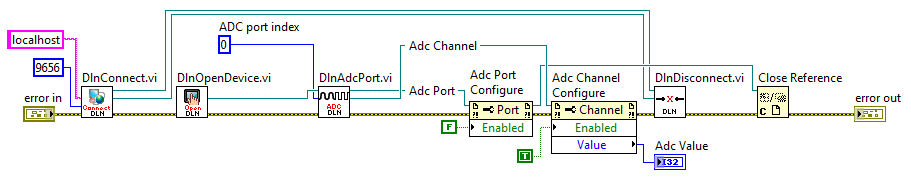
All components are connected sequentially and all error inputs and outputs should be connected. First, we call DlnConnect.vi component and connect to proper inputs port and host values. Then we call DlnOpenDevice.vi component, which opens any connected DLN-series device. DlnAdcPort.vi gets Dln.Device reference and port number as inputs and we get Dln.Adc.Port and Dln.Adc.Channel references as outputs. Connect Dln.Adc.Port and Dln.Adc.Channel references outputs to Property Nodes. To add Port or Channel properties right-click on Port Property Node choose Add Element, then right click again on the new element and choose "Select Property" list. After property is added you can change property to read or write also by right-clicking on property element.
After all operations with ADC module are done, close Dln.Device reference and finally call DlnDisconnect.vi to close connection with Dln Server and Dln.Library reference.
DeviceRemovedEventExample.vi
DeviceRemovedEventExample.vi shows how to use events. While example execution, application is waiting for events and message is shown, if event is raised.
Application Block Diagram is shown below.
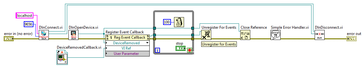
All components are connected sequentially and all error inputs and outputs should be connected. First, we call DlnConnect.vi component with port and host values as inputs. Then we call DlnOpenDevice.vi component, which opens any connected DLN-series device. Next we call Register Event Callback function and connect Dln.Device reference to Register Event Callback function reference input and choose event (in our case it is DeviceRemoved event). Our next step is to create callback function, which will contain code, that should be executed in case of event is raised. Connect callback function to VI reference input of Register Event Callback function.
Callback function DeviceRemovedCallback.vi is shown below.
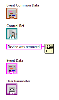
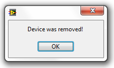
By default, callback function contains Event Common Data, Control Ref, Event Data and User Parameter. For our example we added One Button Dialog with message "Device was removed!". So when event is raised we'll see this message.
To make possible waiting for event, While Loop was added with interval of 100 ms and stop button. If you press stop button application will close. After application is closed, we should call Unregister For Events and Close Reference functions. with unregister all events associated with event registration refnum and close Dln.Device reference accordingly. Finally DlnDisconnect.vi is called, which closes connection with Dln Server and Dln.Library reference.
GetVersionExample.vi
GetVersionExample.vi demonstrates how to retreive information about hardware, library, server and firmware versions.
Application Block Diagram is shown below.
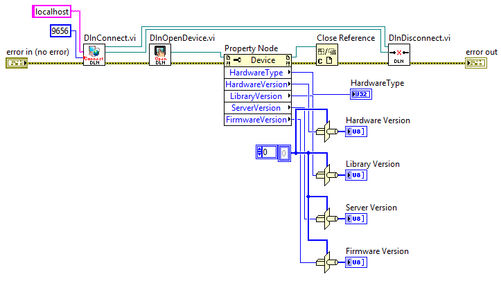
All components are connected sequentially and all error inputs and outputs are connected. First, we call DlnConnect.vi component and connect to proper inputs port and host values. Then we call DlnOpenDevice.vi component, it opens any connected DLN-series device and returns its reference. Add Property Node and connect Dln.Device reference output from DlnOpenDevice.vi. To add Device properties right-click on Property Node and choose "Add Element", then right-click again on the new element and choose "Select Property" and click property name to add it. After property is added you can change property to read or write by right-clicking on property name and choosing correct operation. You can read "Hardware Type", "Hardware Version", "Library Version", "Server Version" and "Firmware Version" properties.
After all operations are done, close Dln.Device reference and finally call DlnDisconnect.vi to close connection with Dln Server and Dln.Library reference.
GpioExample.vi
GpioExample.vi demonstrates how to set and get properties values of GPIO pins.
Application Block Diagram is shown below.
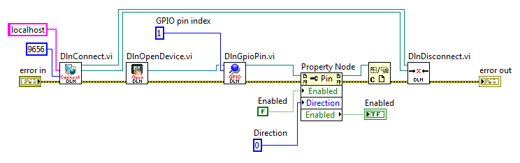
All components are connected sequentially and all error inputs and outputs should be connected. First, we call DlnConnect.vi component and connect to proper inputs port and host values. Then we call DlnOpenDevice.vi component, which opens any connected DLN-series device. DlnGpioPin.vi gets Dln.Device reference and pin number index as inputs and we get Dln.Gpio.Pin reference as output. Connect Dln.Gpio.Pin reference output to Property Node. To add Pin properties right-click on Property Node function and choose Add Element, then right click again on the new element and choose "Select Property" list. After property is added you can change property to read or write also by right-clicking on property element.
After all operations with ADC module are done, close Dln.Device reference and finally call DlnDisconnect.vi to close connection with Dln Server and Dln.Library reference.
I2cMasterExample.vi
I2cMasterExample.vi demonstrates how to set and get properties values of I2C Master port and call methods for transferring data through I2C Master nterface.
Application Block Diagram is shown below.
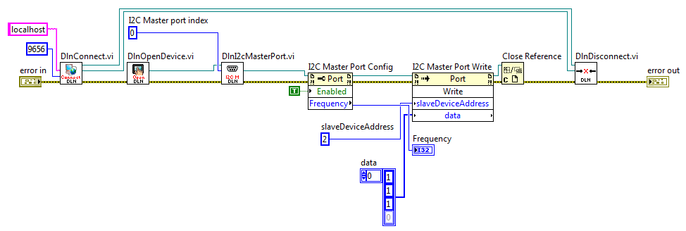
All components are connected sequentially and all error inputs and outputs should are connected.
First, we call DlnConnect.vi component and connect to proper inputs port and host values.
Then we call DlnOpenDevice.vi component, which opens any connected DLN-series device.
DlnI2cMasterPort.vi gets Dln.Device reference and I2C port index number as inputs and we get Dln.I2cMaster.Port reference as output. Connect Dln.I2cMaster.Port reference output to Property Node to configure properties. To add port properties right-click on Port Property Node, choose Add Element, then right-click again on the new element and choose "Select Property" list. After property is added you can change property to read or write by right-clicking on property element. Connect Dln.I2cMaster.Port reference output to Invoke Node to execute available methods.
In this example Write method is called with slaveDeviceAddress and Data parameter as inputs.
After all operations with I2C Master module are done, close Dln.Device reference by calling Close Reference component. Finally call DlnDisconnect.vi to close connection with Dln Server and Dln.Library reference.
I2cSlaveExample.vi
I2cSlaveExample.vi demonstrates how to set and get properties values of I2C Slave port and call methods for transferring data through I2C Slave Interface.
Application Block Diagram is shown below.
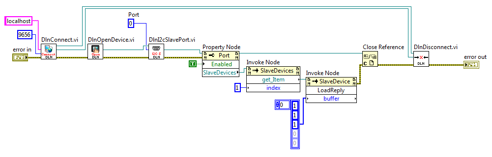
All components are connected sequentially and all error inputs and outputs are connected. First, we call DlnConnect.vi component and connect to proper inputs port and host values. Then we call DlnOpenDevice.vi component, which opens any connected DLN-series device. DlnI2cSlavePort.vi gets Dln.Device reference and port index number as inputs and we get Dln.I2cSlave.Port reference as output. Connect Dln.I2cSlave.Port reference output to Property Node to configure properties. To add Port properties right-click on Port Property Node choose Add Element, then right click again on the new element and choose "Select Property" list. After property is added you can change property to read or write also by right-clicking on property element. Connect Dln.I2cSlave.Port reference output to Invoke Node to execute available methods. In this example Write method is called with slave device address and data parameters.
After all operations with I2C Slave module are done, close Dln.Device reference and finally call DlnDisconnect.vi to close connection with Dln Server and Dln.Library reference.
PulseCounterExample.vi
PulseCounterExample.vi demonstrates how to set and get properties values of Pulse Counter port.
Application Block Diagram is shown below.
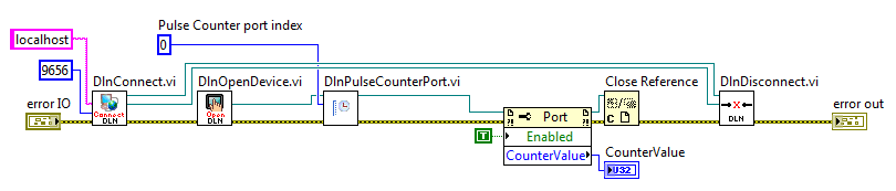
All components are connected sequentially and all error inputs and outputs should be connected. First, we call DlnConnect.vi component and connect to proper inputs port and host values. Then we call DlnOpenDevice.vi component, which opens any connected DLN-series device. DlnPulseCounterPort.vi gets Dln.Device reference and port number as inputs and we get Dln.PulseCounter.Port reference as output. Connect Dln.PulseCounter.Port reference output to Property Nodes. To add Port or Channel properties right-click on Port Property Node and choose Add Element, then right-click again on the new element and choose "Select Property". After property is added, you can change property to read or write by right-clicking on property name.
After all operations with Pulse Counter module are done, close Dln.Device reference and finally call DlnDisconnect.vi to close connection with Dln Server and Dln.Library reference.
PwmExample.vi
PwmExample.vi demonstrates how to set and get properties values of Pwm port and its channels.
Application Block Diagram is shown below.
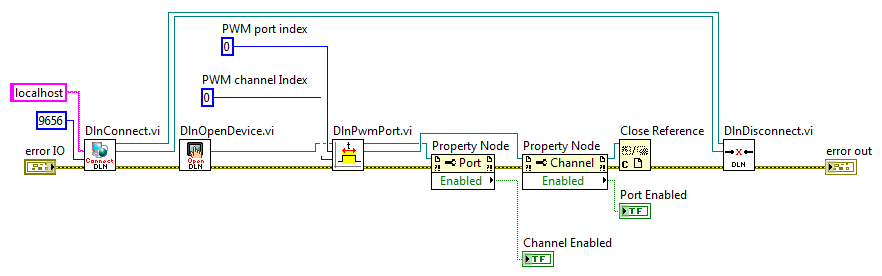
All components are connected sequentially and all error inputs and outputs should be connected. First, we call DlnConnect.vi component and connect to proper inputs port and host values. Then we call DlnOpenDevice.vi component, which opens any connected DLN-series device. DlnPwmPort.vi gets Dln.Device reference and port number as inputs and we get Dln.Pwm.Port and Dln.Pwm.Channel references as outputs. Connect Dln.Pwm.Port and Dln.Pwm.Channel references outputs to Property Nodes. To add Port or Channel properties right-click on Port Property Node choose Add Element, then right click again on the new element and choose "Select Property" list. After property is added you can change property to read or write also by right-clicking on property element.
After all operations with PWM module are done, close Dln.Device reference and finally call DlnDisconnect.vi to close connection with Dln Server and Dln.Library reference.
SetDeviceIdExample.vi
SetDeviceIdExample.vi demonstrates how to set and retrieve connected DLN-series adapter ID number.
Application Block Diagram is shown below.
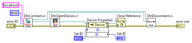
It is seen that all components are connected sequentially and all error inputs and outputs are connected. First, we call DlnConnect.vi component and connect to proper inputs port and host values. Then we call DlnOpenDevice.vi component, it opens any connected DLN-series device and returns its reference. Add Property Node and connect Dln.Device reference output from DlnOpenDevice.vi. To add Device properties right-click on Property Node and choose "Add Element", then right-click again on the new element and choose "Select Property" and click property name to add it. After property is added you can change property to read or write by right-clicking on property name and choosing correct operation. After ID property is added you can assign new ID value or retrieve current.
After all operations are done, close Dln.Device reference and finally call DlnDisconnect.vi to close connection with DLN Server and Dln.Library reference.
SpiMasterExample.vi
SpiMasterExample.vi demonstrates how to set and get properties values of Spi Master port and call methods for transferring data through SPI Master nterface.
Application Block Diagram is shown below.
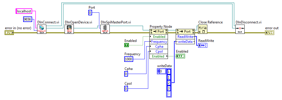
All components are connected sequentially and all error inputs and outputs should be connected. First, we call DlnConnect.vi component and connect to proper inputs port and host values. Then we call DlnOpenDevice.vi component, which opens any connected DLN-series device. DlnSpiMasterPort.vi gets Dln.Device reference and port index number as inputs and as output we get Dln.SpiMaster.Port reference. Connect Dln.SpiMaster.Port reference output to Property Node to config properties. To add Pin properties right-click on Port Property Node choose Add Element, then right click again on the new element and choose "Select Property" list. After property is added you can change property to read or write also by right-clicking on property element. Connect Dln.SpiMaster.Port reference output to Invoke Node to excecute available methods. In this example ReadWrite method is called.
After all operations with ADC module are done, close Dln.Device reference and finally call DlnDisconnect.vi to close connection with Dln Server and Dln.Library reference.
SpiSlaveExample.vi
SpiSlaveExample.vi demonstrates how to set and get SPI Slave port properties values and call methods for transferring data through SPI Slave Interface.
Application Block Diagram is shown below.
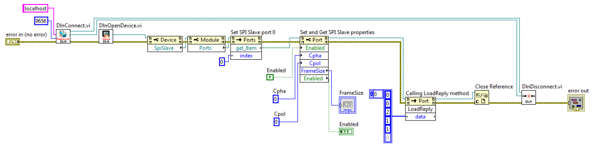
All components are connected sequentially and all error inputs and outputs should be connected. First, we call DlnConnect.vi component and connect to proper inputs port and host values. Then we call DlnOpenDevice.vi component, which opens any connected DLN-series device. DlnSpiSlavePort.vi gets Dln.Device reference and port index number as inputs and we get Dln.SpiSlave.Port reference as output. Connect Dln.SpiSlave.Port reference output to Property Node to configure properties. To add Port properties right-click on Port Property Node choose Add Element, then right click again on the new element and choose "Select Property" list. After property is added you can change property to read or write also by right-clicking on property element. Connect Dln.I2cSlave.Port reference output to Invoke Node to execute available methods. In this example LoadReply method is used.
After all operations with SPI Slave module is done, close Dln.Device reference and finally call DlnDisconnect.vi to close connection with Dln Server and Dln.Library reference.
UartExample.vi
UartExample.vi demonstrates how to set and get properties values of UART port and call methods for transferring data through UART interface.
Application Block Diagram is shown below.
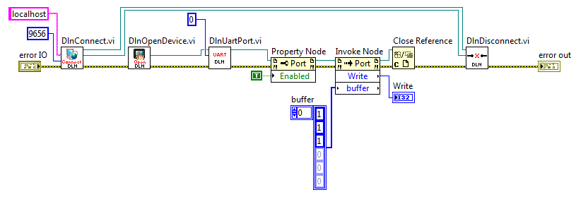
All components are connected sequentially and all error inputs and outputs should are connected. First, we call DlnConnect.vi component and connect to proper inputs port and host values. Then we call DlnOpenDevice.vi component, which opens any connected DLN-series device. DlnUartPort.vi gets Dln.Device reference and port index number as inputs and we get Dln.Uart.Port reference as output. Connect Dln.Uart.Port reference output to Property Node to configure properties. To add port properties right-click on Port Property Node, choose Add Element, then right click again on the new element and choose "Select Property" list. After property is added you can change property to read or write by right-clicking on property element. Connect Dln.Uart.Port reference output to Invoke Node to execute available methods. In this example Write method is called with buffer parameter as input.
After all operations with UART module are done, close Dln.Device reference and finally call DlnDisconnect.vi to close connection with Dln Server and Dln.Library reference.